FW500
Service Manual
9
8/31/2015
2.
Calibration
2.1.
General Calibration
Pressing and holding calibration switch press [POWER] key to go to calibration mode.
User can move to other mode by using [ZERO] key in the calibration mode.
User also moves to other sub-modes for each mode by using [TARE] key.
Please simply follow below procedure to move to other mode.
(1)
Calibration Mode: Pressing and holding “Calibration Switch” press [POWER] key.
(2)
It displays “CAL-0” after “CAL”, and it blinks the version of scale three times.
(3)
Selecting menu: press [TARE].
(4)
ENTER(Setting) : [TARE] key
MODE
Function
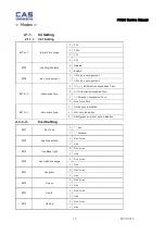
CAL 1
Display normalized AD
CAL 2
Display Keypad infomation-
CAL 3
Weight Setting Mode
→
→
“UnLoad”
[TARE]
→
→
“MIDD”
[TARE] after loading for 1/3 weight
→
→
“FULL”
[TARE] after loading for Full weight
→
→
“MIDD”
[TARE] after loading for 1/3 weight
“END”
CAL 4
Option Setting ( Refer to Table 1)
CAL 5
Display filtered Raw AD
CAL 7
% Calibration
CAL 8
Battery calibration
CAL 9
Gravity constant
CAL 10
Set calibration factor
“Unit”
[TARE]
select 0, 1 (0:kg, 1: lb)
[TARE]
“CAPA”
[TARE]
select capacity
[TARE]
“MCAPA”
[TARE]
select mid-capacity
[TARE]
“W-dP”
[TARE]
Select Decimal Point
[TARE]
“ 1 d ”
[TARE]
Select division
[TARE]
“Dual”
[TARE]
Enable dual interval (0:disable, 1:enable)
[TARE]
“tare”
[TARE]
Enable custom tare (0:disable, 1:enable)
[TARE]
CAL 11
Set nation(00 : OIML , 01 : NTEP , 02: KOREA)
Содержание FW500
Страница 1: ...FW500 Service Manual 1 8 31 2015 FW500 SE SERVICE MANUAL Revision 0 2013 02 19 ...
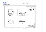
Страница 6: ...FW500 Service Manual 6 8 31 2015 1 4 Dimension ...
Страница 7: ...FW500 Service Manual 7 8 31 2015 1 5 Dimension TILTING DISPLAY TYPE ...
Страница 8: ...FW500 Service Manual 8 8 31 2015 1 6 Sealing method ...
Страница 15: ...FW500 Service Manual 15 8 31 2015 3 2 Circuit Diagram 3 2 1 FW500C Main PCB ...
Страница 16: ...FW500 Service Manual 16 8 31 2015 3 2 2 FW500C Rear Display PCB ...
Страница 17: ...FW500 Service Manual 17 8 31 2015 3 2 3 FW500E Main PCB ...
Страница 18: ...FW500 Service Manual 18 8 31 2015 ...
Страница 19: ...FW500 Service Manual 19 8 31 2015 3 2 4 FW500 E Rear Display PCB ...
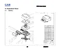
Страница 20: ...FW500 Service Manual 20 8 31 2015 4 Exploded View 4 1 FW500 ...
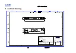
Страница 21: ...FW500 Service Manual 21 8 31 2015 5 Load Cell drawing 25 112 15 112 SW spring element 2090501 00 ...
Страница 22: ...FW500 Service Manual 22 8 31 2015 6 Part Location 6 1 FW500C Main PCB Top Bottom ...
Страница 23: ...FW500 Service Manual 23 8 31 2015 6 2 FW500E Main PCB Top Bottom ...
Страница 24: ...FW500 Service Manual 24 8 31 2015 6 3 FW500C Rear Display PCB Top Bottom ...
Страница 25: ...FW500 Service Manual 25 8 31 2015 6 4 FW500E Rear Dislpay PCB Top Bottom ...


