FW500
Service Manual
12
8/31/2015
(7)
Input a capability by using [ZERO] key.
(8)
Press [TARE] key, and then “MCAPA“ message blinks.“0005” will be shown. The first
digit,”0” will blink. It means a mid-capability is “05 (calibration unit, kg or lb)”
(9)
Input a capability by using [ZERO] key.
(10)Press [TARE] key, and then “W-dP “ message blinks.“3” will be shown. The first
digit,”3” will blink. It means a weight decimal point is “3 (will display 0.000)”
(11)Input a weight decimal point by using [ZERO] key.
(12) Press [TARE] key, and then “1d “ message blinks.“0.005” will be shown. The third
digit,”0”
will blink. It means a division is “0.005 (calibration unit, kg or lb)”
(13) Input a division by using [ZERO] key.
(14) Press [TARE] key, and then “dual “ message blinks.“1” will be shown. The third
digit,”1”
will blink. It means a dual interval is disable. (0 : disable, 1 : enable)”
(15) Input a dual interval enable by using [ZERO] key.
(16) Press [TARE] key to save the calibration factor, and “C-10 ” message will be shown.
2.1.5.
Displaying Real A/D Value (C-5)
Display Raw AD
Содержание FW500
Страница 1: ...FW500 Service Manual 1 8 31 2015 FW500 SE SERVICE MANUAL Revision 0 2013 02 19 ...
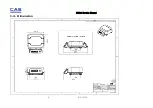
Страница 6: ...FW500 Service Manual 6 8 31 2015 1 4 Dimension ...
Страница 7: ...FW500 Service Manual 7 8 31 2015 1 5 Dimension TILTING DISPLAY TYPE ...
Страница 8: ...FW500 Service Manual 8 8 31 2015 1 6 Sealing method ...
Страница 15: ...FW500 Service Manual 15 8 31 2015 3 2 Circuit Diagram 3 2 1 FW500C Main PCB ...
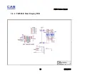
Страница 16: ...FW500 Service Manual 16 8 31 2015 3 2 2 FW500C Rear Display PCB ...
Страница 17: ...FW500 Service Manual 17 8 31 2015 3 2 3 FW500E Main PCB ...
Страница 18: ...FW500 Service Manual 18 8 31 2015 ...
Страница 19: ...FW500 Service Manual 19 8 31 2015 3 2 4 FW500 E Rear Display PCB ...
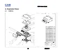
Страница 20: ...FW500 Service Manual 20 8 31 2015 4 Exploded View 4 1 FW500 ...
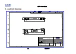
Страница 21: ...FW500 Service Manual 21 8 31 2015 5 Load Cell drawing 25 112 15 112 SW spring element 2090501 00 ...
Страница 22: ...FW500 Service Manual 22 8 31 2015 6 Part Location 6 1 FW500C Main PCB Top Bottom ...
Страница 23: ...FW500 Service Manual 23 8 31 2015 6 2 FW500E Main PCB Top Bottom ...
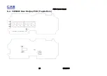
Страница 24: ...FW500 Service Manual 24 8 31 2015 6 3 FW500C Rear Display PCB Top Bottom ...
Страница 25: ...FW500 Service Manual 25 8 31 2015 6 4 FW500E Rear Dislpay PCB Top Bottom ...


