


49
4.5 Printer Hardware
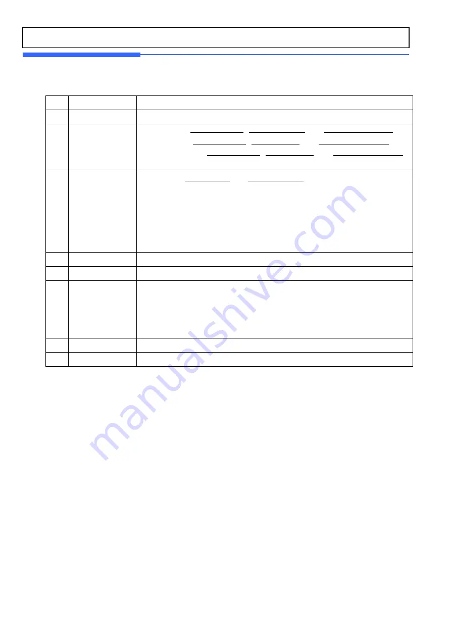
No.
Sub-menus
Description
1
Print Mode
Select label, ticket, continuous label mode.
2
Label / Ticket
Size
Lable mode: “Width(60)”, “Height(40)” and “Gap length(2)”
Ticket mode: “Width(60)”, “Feed(20)” and “End Margin(5)”
Continous Label: “Width(60)”, “Feed(40)” and “End Margin(2)”
* ( ) are default value.
3
Sensor
Calibration
Enter the “Gap(128)” and “Peel(128)” values for printing sensor
calibration.
* The values in ( ) are default.
* If you press “TEST” key, Gap and Peel values are adjusted
automatically.
* In case of Ticket mode, Gap value is not saved.
4
Sensor & Motor Setting Peel-off sensor, Rewind Motor, Label Paper type.
5
Print Intensity
Set the extent of intensity of label (ticket) printed.
6
Adjust Feed
Length
Set adjusting values of feed length.
This value can be from -200 to +200. You can change sign(+,-) by
pressing ZERO key.
+ value will print higher than THP.
* Pressing “TEST” key automatically feeds to adjust the feed length.
7
Label Pre-print You can set preprint length.
8
Printer Initialize You can reset printer.
4.5.1 Print Mode (Menu Code 8310)
(Calibration MENU -> 3. Printer Hardware -> 1. Print Mode)
Press “1” to get into “PRINT MODE.”
You can select “0” for Label mode, “1” for Ticket mode or “2” for Continuous Label mode.
Press “PRINT” to save current selection.
4.5.2 Label/Ticket Size (Menu Code 8320)
(Calibration MENU -> 3. Printer Hardware -> 2. Label/Ticket Size)
You can input “Width,” “Height,” “Gap Length” of label manually.
“TEST” key will automatically measures current label.
* Case of ticket mode “TICKET SIZE” will display and “TEST” key will not function.
Содержание CL5000 Series
Страница 1: ...1 CL5000 Series CL5000 CL5500 Service Manual English Rev 2011 04 07 ...
Страница 10: ...10 ...
Страница 14: ...14 Pole Type G Self service Type Double body Type CL5500 ONLY ...
Страница 16: ...16 TYPE III CL5000 G TYPE Ⅳ CL5500 D ...
Страница 18: ...18 CL5000 H ...
Страница 19: ...19 CL5500 D ...
Страница 33: ...33 CL5500 D ...
Страница 55: ...55 5 Servicing Parts Replacement ...
Страница 56: ...56 ...
Страница 61: ...61 CL5500 D 1 Remove head cover bolt 4 bolt 2 Open up from printer side to disassamble head cover ...
Страница 78: ...78 8 Schematic Diagrams 8 1 1 System Block Diagram CL5000 B P R G S H ...
Страница 79: ...79 8 1 2 System Block Diagram CL5500 D ...
Страница 80: ...80 8 1 3 System Block Diagram CL5500 B P R H S ...
Страница 81: ...81 8 2 1 Connection Diagram CL5000 B P R G S H ...
Страница 82: ...82 8 2 2 Connection Diagram CL5500 D ...
Страница 83: ...83 8 2 3 Connection Diagram CL5500 BPRHS ...
Страница 84: ...84 8 3 I O Pin Connection CL5000 B P R G S H ...
Страница 85: ...85 8 3 I O Pin Connection CL5500 ...
Страница 86: ...86 9 Exploded Views 9 1 Double Body Type Head cover A ssy ...
Страница 87: ...87 9 2 Double Body Type Cartridge A ssy ...
Страница 88: ...88 9 3 Double Body Type Base bracket A ssy ...
Страница 89: ...89 9 4 Double Body Type Door A ssy ...
Страница 90: ...90 9 5 Double Body Type Head A ssy ...
Страница 91: ...91 9 6 Double Body Type Tray A ssy ...
Страница 92: ...92 9 7 Double Body Type Upper A ssy ...
Страница 93: ...93 9 8 Double Body Type Platform A ssy ...
Страница 94: ...94 9 9 Double Body Type Body A ssy ...
Страница 95: ...95 9 10 Lan card ...
Страница 100: ...100 8 1 9 1 10 1 11 1 12 1 13 1 14 1 ...
Страница 124: ...124 No IMAGE Part Code Parts Name DESCRIPTION Unit Q ty 1 LLATP0153G070001 TPN 15L 1 12 EA 1 3 1 LOAD CELL ASS Y ...
Страница 125: ...125 11 Revision 11 Mar 2005 Add Sealing Method Adjust Chapter number 15 Apr 2010 Add CL5500 D Type ...


