185
Filter Drier
Replace whenever the moisture/liquid indicator shows mois
-
ture in the system or when the system was opened for service.
Liquid Line Service Valves
Use caution when closing liquid line service valves. The ex
-
pansion of a trapped liquid can create dangerously high pres
-
sures. Remove refrigerant immediately from trapped sections
or attach a hose from the high side to the low side of the system
to provide relief. If equipped with a liquid line solenoid valve
in the evaporator section, it will be closed during the off-cycle.
This creates the potential for a liquid trap between the solenoid
valve and a closed service valve. Remove refrigerant immedi
-
ately from the section or attach a hose for relief.
Protective Devices
COMPRESSOR PROTECTION
Overcurrent
Each compressor has one manual reset, calibrated trip, magnet
-
ic circuit breaker. Do not bypass connections or increase the
size of the circuit breaker to correct trouble. Determine the
cause and correct it before resetting the breaker.
Overtemperature
Each compressor has a protector to protect it against excessive
-
ly high discharge gas temperatures.
Additionally, some units contain Copeland compressors
equipped with advanced scroll temperature protection (ASTP).
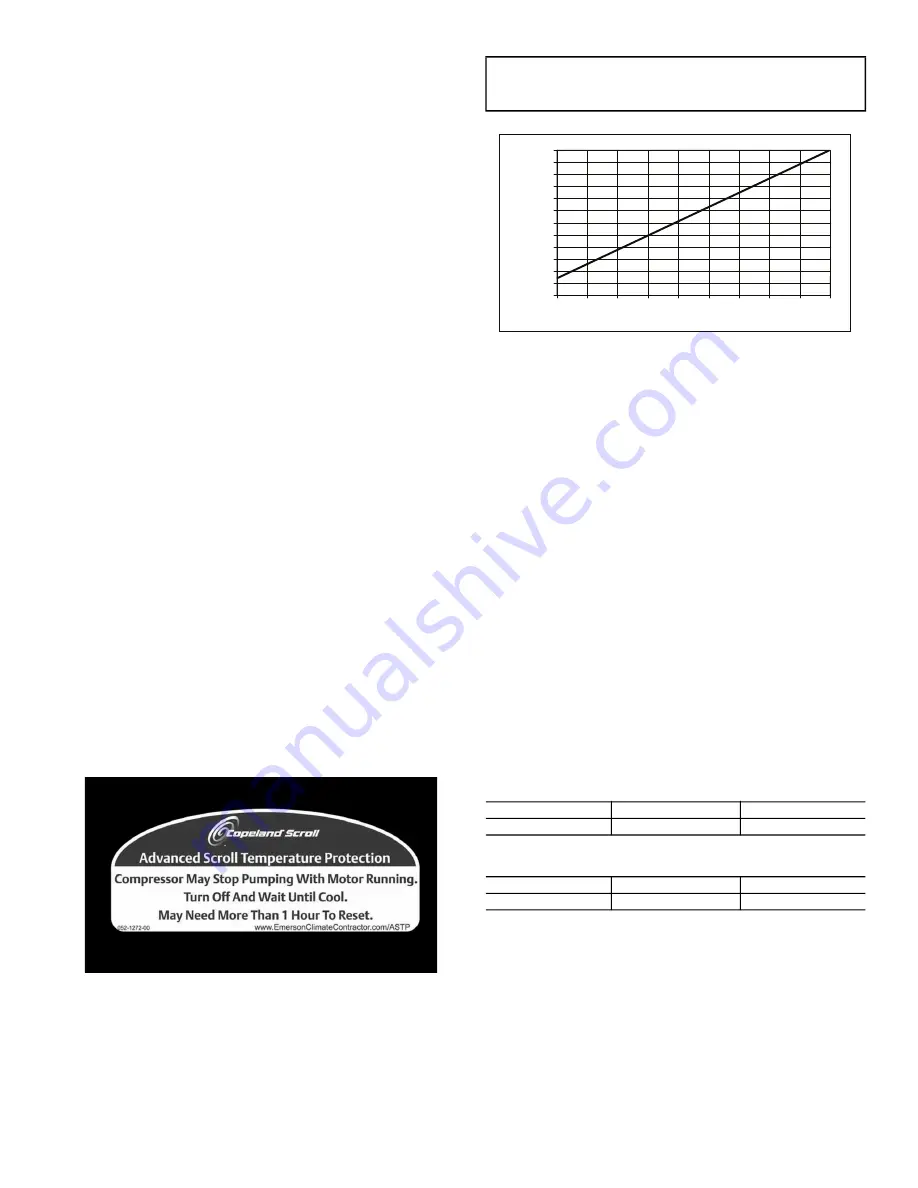
A label located above the terminal box identifies Copeland
Scroll compressor models that contain this technology. See
Fig. 81. Advanced scroll temperature protection is a form of in
-
ternal discharge temperature protection that unloads the scroll
compressor when the internal temperature reaches approxi
-
mately 300°F. At this temperature, an internal bi-metal disk
valve opens and causes the scroll elements to separate, which
stops compression. Suction and discharge pressures balance
while the motor continues to run. The longer the compressor
runs unloaded, the longer it must cool before the bi-metal disk
resets. See Fig. 82.
To manually reset ASTP, the compressor should be stopped
and allowed to cool. If the compressor is not stopped, the mo
-
tor will run until the motor protector trips, which occurs up to
90 minutes later. Advanced scroll temperature protection will
reset automatically before the motor protector resets, which
may take up to 2 hours.
Fig. 81 —
Advanced Scroll Temperature
Protection Label
Crankcase Heater
Each compressor has a crankcase heater to prevent absorption
of liquid refrigerant by oil in the crankcase when the compres
-
sor is idle. Since 115-v power for the crankcase heaters is
drawn from the unit control circuit, main unit power must be
on for the heaters to be energized.
Fig. 82 —
Recommended Minimum Cool-Down Time
After Compressor is Stopped*
EVAPORATOR-FAN MOTOR PROTECTION
A manual reset, calibrated trip, magnetic circuit breaker pro
-
tects against overcurrent. Do not bypass connections or in
-
crease the size of the breaker to correct trouble. Determine the
cause and correct it before resetting the breaker.
CONDENSER-FAN MOTOR PROTECTION
Each condenser-fan motor is internally protected against
over-temperature. They are also protected against a severe
over-current condition by manual reset, calibrated trip, mag
-
netic circuit breakers on a common circuit. As with the circuit
breakers, do not bypass connections or increase breaker size
to correct trouble. Determine the cause and correct it before
resetting the breaker.
HIGH-PRESSURE SWITCHES
Settings for these switches are shown in Tables 110 and 111. If
either switch trips, that refrigerant circuit will be automatically
locked out by the controls. To reset, set
ALARMS
R.CUR
=
YES.
Table 110 —
Pressure Switch Settings (psig)
Table 111 —
Pressure Switch Settings (kPa)
Temperature Relief Devices
All units have temperature relief devices to protect against dam
-
age from excessive pressures caused by extreme high tempera
-
tures (i.e., fire). These devices protect the high and low side.
Control Circuit, 115 V
This control circuit is protected against overcurrent by a 10-amp
circuit breaker. Breaker can be reset. If it trips, determine cause
of trouble before resetting.
IMPORTANT: After a prolonged shutdown or service
job, energize the crankcase heaters for 24 hours before
starting the compressor.
SWITCH
CUTOUT
CUT-IN
High
650
10
500
15
SWITCH
CUTOUT
CUT-IN
High
4482
69
3447
103
0
10
20
30
40
50
60
70
80
90
100
110
120
0
10
20
30
40
50
60
70
80
90
Recommended Cooling
Time
(Min
u
te
s
)
Compre
ss
or Unlo
a
ded R
u
n Time (Min
u
te
s
)
* Times are approximate.
NOTE: Various factors, including high humidity, high ambient tem-
perature, and the presence of a sound blanket will increase cool-
down times.
Содержание WeatherExpert 48N2
Страница 135: ...135 Fig 18 48 50N Typical Power Schematic Nominal 075 Ton Unit Shown ...
Страница 136: ...136 Fig 19 48 50N Typical Power Schematic Nominal Ton 90 150 Units Shown ...
Страница 137: ...137 Fig 20 48 50N Main Base Board Input Output Connections ...
Страница 138: ...138 Fig 21 48 50N RXB EXB CEM Input Output Connections a48 9307 ...
Страница 139: ...139 Fig 22 48 50N EXV SCB Input Output Connections a48 9308 ...
Страница 140: ...140 Fig 23 48N Typical Modulating Gas Heat Unit Control Wiring ...
Страница 141: ...141 Fig 24 50N Typical Electric Heat Unit Control Wiring ...
Страница 144: ...144 Fig 27 48N Typical Gas Heat Section Wiring Nominal Ton 120 to 150 Units ...
Страница 145: ...145 Fig 28 48 50N Typical Power Component Control Wiring 460 v ...
Страница 146: ...146 Fig 29 48 50N Component Control Wiring 575 v Nominal Ton 075 to 150 Units ...
Страница 147: ...147 Fig 30 48 50N Component Arrangement Power Box ...
Страница 148: ...148 Fig 31 48 50N Component Arrangement Control Box ...
Страница 168: ...168 Fig 47 Sensor and Ignition Position Fig 48 Combustion Blower Details SENSOR DETAILS IGNITION DETAILS ...
Страница 240: ...240 APPENDIX D VFD INFORMATION CONT Fig G VFD Bypass Wiring Diagram WHEN USED ...


