INSPECT WIRING AND RECORD ELECTRICAL DATA:
RATINGS:
Motor Voltage
Motor(s) Amps
Oil Pump Voltage
Starter Amps
Line Voltages:
Motor
Oil Pump
Controls/Oil Heater
FIELD-INSTALLED STARTERS ONLY:
Check continuity T1 to T1, etc. (Motor to starter, disconnect motor leads T4, T5, T6.) Do not megger solid-state starters, disconnect
leads to motor and megger the leads.
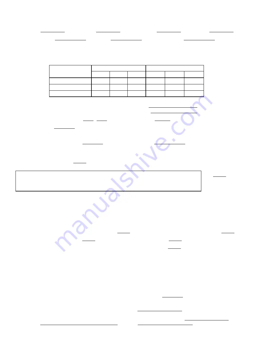
MEGGER MOTOR
‘‘PHASE TO PHASE’’
‘‘PHASE TO GROUND’’
T1-T2
T1-T3
T2-T3
T1-G
T2-G
T3-G
10-Second Readings:
60-Second Readings:
Polarization Ratio:
STARTER:
Electro-Mechanical
M
Solid-State
M
Manufacturer
Serial Number
Motor Load Current Transformer Ratio
:
Signal Resistor Size
Ohms
Transition Timer Time
Seconds
Check Magnetic Overloads
Add Dash Pot Oil
Yes
M
No
M
Solid-State Overloads
Yes
M
No
M
Solid State Starter:
Torque Setting
O’Clock
Ramp Setting
Seconds
CONTROLS: SAFETY, OPERATING, ETC.
Perform Controls Test (Yes/No)
PIC CAUTION
COMPRESSOR MOTOR AND CONTROL CENTER MUST BE PROPERLY AND INDIVIDUALLY CON-
NECTED BACK TO THE EARTH GROUND IN THE STARTER. (IN ACCORDANCE WITH CERTIFIED
DRAWINGS).
Yes
RUN MACHINE:
Do these safeties shut down machine?
Condenser Water Flow Switch
Yes
M
No
M
Chilled Water Flow Switch
Yes
M
No
M
Pump Interlocks
Yes
M
No
M
INITIAL START:
Line Up All Valves in Accordance With Instruction Manual:
Start Water Pumps and Establish Water Flow
Oil Level OK and Oil Temperature OK
Check Oil Pump Rotation-Pressure
Check Compressor Motor Rotation (Motor End Sight Glass) and Record:
Clockwise
Restart Compressor, Bring Up To Speed. Shut Down. Any Abnormal Coastdown Noise?
Yes*
M
No
M
*If yes, determine cause.
START MACHINE AND OPERATE. COMPLETE THE FOLLOWING:
A: Trim Charge and Record Under Charge Refrigerant Section on page 51.
B: Complete Any Remaining Control Calibration and Record Under Controls Section (pages 11-36).
C: Take At Least 2 Sets of Operational Log Readings and Record.
E: After Machine Has Been Successfully Run and Set Up, Shut Down and Mark Shutdown Oil and Refrigerant Levels.
F: Give Operating Instructions to Owner’s Operating Personnel.
Hours Given:
Hours
G: Call your Carrier factory representative to report chiller start-up.
SIGNATURES:
DATE
CARRIER
CUSTOMER REPRESENTATIVE
TECHNICIAN
DATE
4
Содержание PC211
Страница 317: ...Figure 1 19XL Identification ...
Страница 318: ...Figure 2A Front View Typical 19XL Components Design I See next page for Rear View ...
Страница 319: ...Figure 2A Rear View Typical 19XL Components Design I ...
Страница 320: ...Figure 2B Front View Typical 19XL Components Design II See next page for Rear View ...
Страница 321: ...Figure 2B Rear View Typical 19XL Components Design II ...
Страница 322: ...Figure 3 Refrigerant Motor Cooling and Oil Cooling Cycles ...
Страница 323: ...Figure 4 Lubrication System ...
Страница 324: ...Figure 5 Cutler Hammer Solid State Starter Internal View ...
Страница 325: ...Figure 6 Benshaw Inc Solid State Starter Internal View ...
Страница 326: ...Figure 7 Typical Starter Front View Solid State Starter Shown ...
Страница 327: ...Figure 8 19XL Controls and Sensor Locations ...
Страница 328: ...Figure 9 Control Sensors Temperature ...
Страница 329: ...Figure 10 Control Sensors Pressure Transducer Typical ...
Страница 330: ...Figure 11 Control Panel Front View with Options Module ...
Страница 331: ...Figure 12 Power Panel with Options ...
Страница 332: ...Figure 13 LID Default Screen ...
Страница 333: ...Figure 14 LID Service Screen ...
Страница 334: ...Figure 15 Example of Point Status Screen Status01 ...
Страница 335: ...Figure 16 19XL Menu Structure ...
Страница 336: ...Figure 17 19XL Service Menu Structure ...
Страница 337: ...Figure 18 Example of Time Schedule Operation Screen ...
Страница 338: ...Figure 19 Example of Set Point Screen ...
Страница 339: ...Figure 20 19XL Hot Gas Bypass Surge Prevention ...
Страница 340: ...Figure 21 19XL with Default Metric Settings ...
Страница 341: ...Figure 22 Example of Attach to Network Device Screen ...
Страница 342: ...Figure 23 Example of Holiday Period Screen ...
Страница 344: ...Figure 25 Typical Wet Bulb Type Vacuum Indicator ...
Страница 345: ...Figure 26 19XL Leak Test Procedures ...
Страница 346: ...Figure 27 Typical Optional Pumpout System Piping Schematic with Storage Tank ...
Страница 347: ...Figure 28 Typical Optional Pumpout System Piping Schematic without Storage Tank ...
Страница 348: ...Figure 29 Dehydration Cold Trap ...
Страница 349: ...Figure 30 Benshaw Inc Solid State Starter Power Stack ...
Страница 350: ...Figure 31 Ramp Up and Starting Torque Potentiometers ...
Страница 351: ...Figure 32 Typical Potentiometer Adjustment ...
Страница 352: ...Figure 33 Typical Cutler Hammer Solid State Starter ...
Страница 353: ...Figure 34 Correct Motor Rotation ...
Страница 356: ...Figure 37 Optional Pumpout System ...
Страница 357: ...Figure 38 Guide Vane Actuator Linkage ...
Страница 358: ...Figure 39 19XL Float Valve Designs ...
Страница 359: ...Figure 40 Optional Pumpout System Controls ...
Страница 360: ...Figure 41 PSIO Module Address Selector Switch Locations and LED Locations ...
Страница 361: ...Figure 42 LID Module Rear View and LED Locations ...
Страница 362: ...Figure 43 Processor PSIO Module ...
Страница 363: ...Figure 44 Starter Management Module SSM ...
Страница 364: ...Switch Setting Option Module 1 Option Module 2 S1 S2 6 4 7 2 Figure 45 Options Module ...
Страница 365: ...Figure 46 Typical Benshaw Inc Solid State Starter Internal View ...
Страница 366: ...Figure 47 Resistance Check ...
Страница 367: ...Figure 48 SCR and Power Poles ...
Страница 368: ...Figure 49 Typical Cutler Hammer Solid State Starter Internal View ...
Страница 369: ...Figure 50 Cutler Hammer Terminal Functions ...
Страница 370: ...Figure 51 Solid State Starter General Operation Troubleshooting Guide Typical ...
Страница 371: ...Figure 52 Solid State Starter Starter Fault Motor Will Not Start Troubleshooting Guide Typical ...
Страница 373: ...Figure 54 Compressor Fits and Clearances Continued ...
Страница 374: ...Figure 55 Compressor Fits and Clearances Continued ...