MULTI-STAGE SEVEN DAY PROGRAMMABLE
HEAT
PUMP
HEAT
COOL
&
72
74
70
Am
C
OOL
H
EAT
AUTO
I2:00
M
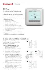
Installation Instructions
TSTATCCPF701
TSTATBBPF701
P374-1100FM
Digital Thermostat
NOTE: Read the entire instruciton manual before starting the installation.
Form: IM-TSTAT-08
Cancels:
Printed in U.S.A.
Catalog No. 13TS-TA34