38
For best results wash coils from discharge side and wash back to-
ward the fan or unit return filters. Clean coils with a vacuum
cleaner, fresh water, compressed air, or a bristle brush (not wire).
Backflush coil to remove debris. Commercial coil cleaners may
also be used to help remove grease and dirt. Steam cleaning is
NOT recommended. Units installed in corrosive environments
should be cleaned as part of a planned maintenance schedule. In
this type of application, all accumulations of dirt should be
cleaned off the coil.
Use a fin comb with teeth of the correct fin spacing when straight-
ening bent or mashed fins.
During heating operation, the vacuum-return system is recom-
mended since it helps eliminate any residual condensate from the
coil.
The steam distribution coils have a significantly reduced possibili-
ty of freeze-ups. They are still susceptible to freezing, however, if
a minimum steam quantity is not maintained where air over the
coil approaches 32°F, or if they are not properly pitched, drained,
trapped and controlled.
The following points should also be considered for freeze protec-
tion of steam distributing coils.
In cases where outside air is admitted to the unit, it should be suffi-
ciently mixed with return air before reaching the coil in order to
avoid cold spots on the coil. It is important that a minimum steam
quantity be maintained when heat is called for to prevent water re-
maining in the tubes and possibly freezing. The ON-OFF type of
steam control is preferred over modulating control where air tem-
perature over the coil approaches 32°F. Make sure that closed out-
side air dampers are sufficiently sealed to prevent air leakage. Low
leak style dampers are recommended.
Make sure that the coil is properly pitched, drained, and trapped so
that condensate drains out of the coil whenever the control valve
shuts off the steam supply.
Checking System Charge
The 50XCW units are shipped with full operating charge. If re-
charging is necessary:
1. Insert thermometer bulb in insulating rubber sleeve on liquid
line near filter drier. Use a digital thermometer for all tem-
perature measurements. DO NOT use a mercury or dial-type
thermometer.
2. Connect refrigerant pressure gage to discharge line near
compressor.
3. After unit condition have stabilized, read head pressure on
discharge line gage.
NOTE: Operate unit a minimum of 15 minutes before check-
ing charge.
4. From standard pressure-temperature chart for R-410A, find
equivalent saturated condensing temperature.
5. Read liquid line temperature on thermometer; then subtract
from saturated condensing temperature. The difference
equals subcooling temperature.
6. Compare the subcooling temperature with the normal tem-
perature listed in Table 13. If the measured liquid line tem-
perature does not agree with the required liquid line
temperature, ADD refrigerant to raise the temperature or
REMOVE refrigerant (using standard practices) to lower the
temperature (allow a tolerance of ± 3°F).
Example:
Head pressure (from gage) 416.4 psig
Saturated condensing temp (from chart) 120°F
Liquid line temp (from thermometer) 100°F
Subcooling (by subtraction) 20°F
*Saturated condensing temperature at compressor minus liquid line
temperature.
NOTE: Do not vent or depressurize unit refrigerant to atmosphere.
Remove and recover refrigerant following accepted practices.
Access Panel Removal
TOP PANEL
Remove 3 to 6 screws, pull out panel and remove.
CONTROL PANEL
Remove 4 screws and remove panel.
BOTTOM PANEL
Remove 3 to 6 screws in bottom panel and lift up to remove panel.
Evaporator-Fan Motor Removal
NOTE: Motor power wires need to be disconnected from control
box terminals before motor is removed from unit.
1. Shut off unit main power supply. Lock out power supply and
tag disconnect locations.
2. Loosen bolts on mounting bracket so that fan belt can be
removed.
3. Disconnect motor power wires from motor terminals.
4. Remove the 4 motor mounting bolts from bottom of motor.
5. Remove motor. Rest motor securely on a high platform such
as a step ladder. Do not allow motor to hang by its power
wires.
Pressure Relief Device
All units are equipped with a fusible-plug type safety relief device
on the refrigerant tubing. The relief setting is 210°F.
Current Protection Device
All units are equipped with a current-sensing lockout relay on
each circuit. This device will lock out the compressor after any
safety trip (high-pressure switch, low-pressure switch, or internal
overload of the compressor) for 5 minutes. Check reason for lock-
out before resetting the device. To reset, turn the thermostat sys-
tem switch to OFF, then back to COOL position.
High and Low-Pressure Switches
The high-pressure switch is located on the compressor discharge
line. The low-pressure switch is located on the suction line.
Oil Charge
All units are factory charged with oil (see Table 1 for compressor
model number). It is not necessary to add oil unless the compres-
sor is removed from the unit. If additional oil is needed, do not use
mineral oils. Only synthetic oils are satisfactory.
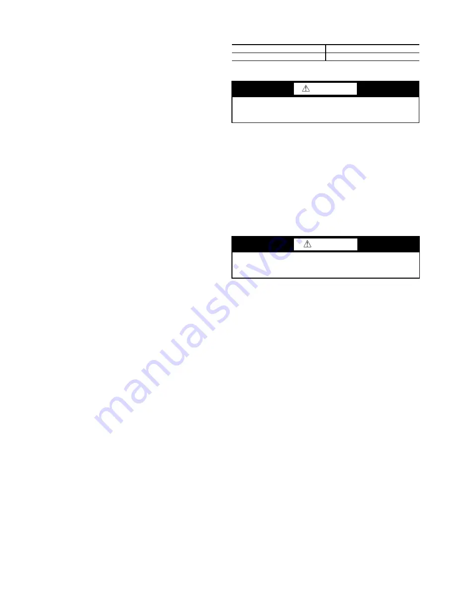
Table 13 — Subcooling Temperature
UNIT 50XCW
SUBCOOLING*
06-24
12°F
WARNING
To prevent personal injury, wear safety glasses and gloves
when handling refrigerant. Do not overcharge system — this
can cause compressor flooding.
CAUTION
Before attempting to remove fan motors or motor mounts,
place a piece of plywood over evaporator coils to prevent coil
damage.


