


38
Wiring Inputs and Outputs
Refer to Table 17 for wiring inputs and outputs.
Table 17 — Input Wiring Specifications
LEGEND
Input – I/O Flex 6126 Controller
The I/O Flex 6126 controller has 12 inputs that accept the sig-
nal types described below.
See Table
Table 18 — I/O Flex 6126 Controller Inputs
BINARY OUTPUTS
The I/O Flex 6126 controller has 6 binary outputs that can be
connected to a maximum of 24 VAC/VDC inputs. Each output is
a dry contact rated at 1A, 24 V maximum and is normally open.
To size output wiring, consider the following when field install-
ing accessories:
• Total loop distance from the power supply to the control-
ler, and then to the controlled device
NOTE: Include the total distance of actual wire. For 2-conductor
wires, this is twice the cable length.
• Acceptable voltage drop in the wire from the controller to
the controlled device
• Resistance (ohms) of the chosen wire gage
• Maximum current (amps) the controlled device requires to
operate
ANALOG OUTPUTS
The I/O Flex 6126 controller has 6 analog outputs that support
voltage or current devices. The controlled device must share the
same ground as the controller and have the following input
impedance:
0 to 10 VDC min 500 ohms
0 to 20 mA min 800 ohms
See Table 20 for a detailed list of standard inputs and outputs.
TO WIRE FIELD ACCESSORIES ON THE I/O FLEX 6126
CONTROLLER OR I/O FLEX EX8160 EXPANDER
1. Turn off power to the I/O Flex 6126 controller.
2. Connect the input or output wiring to the screw terminals on
the controller:
• Connect the shield wire to the GND terminal with the
ground wire.
• For a loop-powered 4 to 20 mA sensor, wire the sensor’s
positive terminal to the + terminal on the I/O Flex 6126
controller’s Aux Power Out Port. Wire the sensor’s nega-
tive terminal to an input’s + terminal.
3. Set the appropriate jumpers on the I/O Flex 6126 controller.
See Table 19.
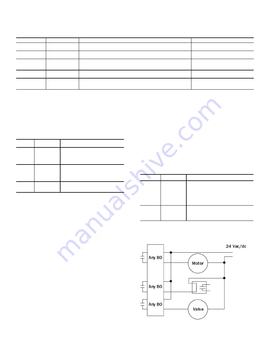
4. Connect the binary output wiring to the screw terminals on
the I/O Flex 6126 controller and to the controlled device
(Fig. 29).
Fig. 29 — Binary Output Diagram
INPUT MAXIMUM
LENGTH
MINIMUM
GAGE
SHIELDING
0-5 VDC
0-10 VDC
1000 feet
(305 meters)
26 AWG
Shielded
0-20 mA
3000 feet
(914 meters)
26 AWG
Shielded or unshielded
Thermistor
Dry contact
Pulse counter
1000 feet
(305 meters)
22 AWG
Shielded
RTD
100 feet
(30 meters)
22 AWG
Shielded
ZS sensor
BACview
Equipment Touch
500 feet
(152 meters)
18 AWG, 4 conductor if BACview is connected to the Rnet
22 AWG, 4 conductor if only RS room sensors are connected to the Rnet
Shielded or unshielded
AWG
—
American Wire Gage
RTD
—
Resistance Temperature Detector
INPUT
SIGNAL TYPE
SUPPORTED
DESCRIPTION
All
Thermistor
RTD
0
–1
0
Vdc
4-2
0
mA
Type 2 (1
0
K
o
hm at 77° F)
.
Input voltages
should be from
0.
489 VDC to 3
.
825 VDC
for thermistors.
All
Dry contact
A 5 VDC wetting voltage detects contact
position
,
resulting in a
0
.5 mA maximum
sense current when the contacts are
closed
.
UI-1
,
UI
-
2
0-2
0
mA
Pulse input
The input impedance of the I/O Flex 6126
controller is
approximately 1 Mohm
.
Table 19 — I/O Flex 6126 Controller Jumper Settings
USE TYPE
DESCRIPTION
Any Input
Thermistor
Dry Contact
0-
5 Vdc
0
–1
0
Vdc
0-2
0
mA RTD
Set each input
’
s Universal Input Mode
Select jumper to the type of signal the input
will receive
Aux
Power
Out Port
Loop-pow-
ered
4-2
0
mA
Set the Select jumper to
+5V or +24V as
required by the sensor
.
Содержание Omnizone 50BVC
Страница 9: ...9 Fig 5 Low Boy Field Split 40 60 Ton 1 3 2 4 1 2 3 4...
Страница 36: ...36 Fig 27 UPM Sequence of Operation SOO Flow Chart...
Страница 42: ...42 Fig 31 I O Flex 6126 Controller Input Modes and Diagram...
Страница 89: ......


