background image

F97CMN and G97CMN: Installation, Start-up, Operating and Service and Maintenance Instructions

Manufacturer reserves the right to change, at any time, specifications and designs without notice and without obligations.

67

A11584

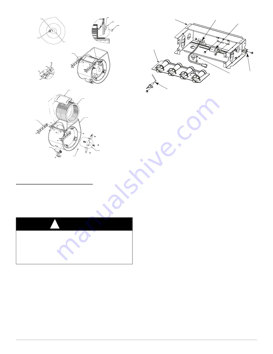
Fig. 66 – Blower Assembly

NOTE: 

Be  sure  to  attach  ground  wire  and  reconnect  blower  harness

plugs to blower motor.

Cleaning Burners and Flame Sensor

The  following  items  must  be  performed  by  a  qualified  service

technician. If the burners develop an accumulation of light dirt or dust,

they may be cleaned by using the following procedure:

NOTE: 

Use  a  back-up  wrench  on  the  gas  valve  to  prevent  the  valve

from rotating on the manifold or damaging the mounting to the burner

assembly.

Refer to 

Fig. 59

.

1. Disconnect power at external disconnect, fuse or circuit breaker.
2. Turn off gas at external shut-off or gas meter.
3. Remove control door and set aside.
4. Turn electric switch on gas valve to OFF.
5. Disconnect the gas pipe from gas valve and remove pipe from the

furnace casing.

6. Disconnect the connector harness from gas valve (Modulating only)

or remove individual wires from terminals on gas valve (All other

models).

7. Disconnect Hot Surface Igniter (HSI) wires from HSI.
8. Disconnect Flame Sensor wire from Flame Sensor.

A11403

Fig. 67 – Burner Assembly

9. Support  the  manifold  and  remove  the  4  screws  that  secure  the

manifold assembly to the burner assembly and set aside. Note the

location of the green/yellow wire and ground terminal.

10. Inspect  the  orifices  in  the  manifold  assembly  for  blockages  or

obstructions. Remove orifice and clean or replace orifice. 

11. Remove the four screws that attach the top plate of the casing to the

furnace.

12. Raise top plate up slightly and prop it up with a small piece of wood

or folded cardboard.

13. Support the burner assembly and remove the screws that attach the

burner assembly to the heat exchanger cell panel.

14. Remove wires from both rollout switches.
15. Slide one-piece burner out of slots on sides of burner assembly.
16. Remove the flame sensor from the burner assembly.
17. (Optional) Remove the Hot Surface Igniter (HSI) and bracket from

the burner assembly.

18. Check  igniter  resistance.  Nominal resistance  is 40 to  70  ohms  at

room temperature and is stable over the life of the igniter.

19. Clean burner with a brush and a vacuum. 
20. Clean the flame sensor with fine steel wool (0000 grade). Do not

use sand paper or emery cloth.

To reinstall burner assembly:

1. Install  the  Hot  Surface  Igniter  (HSI)  and  bracket  in  burner

assembly.

2. Install flame sensor on burner.
3. Align the edges of the one-piece burner with the slots in the burner

assembly and slide the burners forward until they are fully seated in

the burner assembly.

4. Align the orifices in the manifold assembly with the support rings

on the end of the burner.

5. Insert the orifices in the support rings of the burners.

NOTE: 

If manifold does not fit flush against the burner, do not force the

manifold  on  the  burner  assembly.  The  burners  are  not  fully  seated

forward in the burner assembly. Remove the manifold and check burner

positioning  in  the  burner  assembly  assembly  before  re-installing  the

manifold.

6. Attach  the  green/yellow  wire  and  ground  terminal  to  one  of  the

manifold mounting screws. 

7. Install the remaining manifold mounting screws.
8. Check the igniter alignment, see 

Fig. 67

, 

Fig. 68

 and 

Fig. 69

.

9. Attach the wires to the roll-out switches.
10. Align  the  burner  assembly  with  the  openings  in  the  primary  cell

inlet panel and attach the burner assembly to the cell panel.

WARNING

!

ELECTRICAL SHOCK AND FIRE HAZARD

Failure  to  follow  this  warning  could  result  in  personal  injury,  death,

and/or property damage. 

Turn off the gas and electrical supplies to the furnace and install lockout

tag before performing any maintenance or service. Follow the operating

instructions on the label attached to the furnace. 

SET SCREW

MOTOR WHEEL HUB

MOTOR SHAFT FLAT

SCREW

MOTOR ARM

GROMMET

SCREW LOCATION

BLOWER HSG ASSY

BRACKET

BRACKET
ENGAGEMENT

SEE DETAIL 

A

CAPACITOR
OR POWER CHOKE
(WHEN USED)

BRACKET

SCREW 

(GND)

BLOWER HSG ASSY

MOTOR, BLOWER

WHEEL, BLOWER

CUTOFF, BLOWER

DETAIL 

A

FLAME SENSOR
(BELOW BURNER)

FLAME ROLLOUT
SWITCH

BRACKET, IGNITER

IGNITER

BURNER SUPT. ASSY

BURNER ASSY

Содержание F97CMN

Страница 1: ... for Gas Input Rate 61 SERVICE AND MAINTENANCE PROCEDURES 63 Winterization 70 SEQUENCE OF OPERATION 74 PARTS REPLACEMENT INFORMATION GUIDE 78 Most states in the USA and jurisdictions in Canada have laws thatrequire the use of Carbon Monoxide CO alarms with fuel burning products Examples of fuel burning products are furnaces boilers space heaters generators water heaters stoves ranges clothes dryer...

Страница 2: ...to the exterior of the building at a minimum height of eight 8 feet above grade directly in line with the exhaust vent terminal for the horizontally vented gas fueled heating appliance or equipment The sign shall read in print size no less than one half 1 2 inch in size GAS VENT DIRECTLY BELOW KEEP CLEAR OF ALL OBSTRUCTIONS 4 INSPECTION The state or local gas inspector of the side wall horizontall...

Страница 3: ...aintenance or use can cause carbon monoxide poisoning explosion fire electrical shock or other conditions which may cause personal injury or property damage Consult a qualified service agency local gas supplier or your distributor or branch for information or assistance The qualified service agency must use only factory authorized and listed kits or accessories when modifying this product WARNING ...

Страница 4: ... available soap solution made specifically for the detection of leaks to check all connections as specified in the Gas Piping section 6 Always install furnace to operate within the furnace s intended temperature rise range with a duct system which has an external static pressure within the allowable range as specified in the Start Up Adjustments and Safety Check section See furnace rating plate 7 ...

Страница 5: ...pairs may impact warranty coverage For accessory installation details refer to the applicable instruction literature NOTE Remove all shipping materials loose parts bag and literature before operating the furnace see Table 2 Table 2 Loose Parts Bag A12182 Fig 4 Prohibited Installations NOTICE Important Installation and Start up Procedures Failure to follow this procedure may result in a nuisance sm...

Страница 6: ...al Electrical Code NEC NFPA 70 CANADA Current edition of Canadian Electrical Code CSA C22 1 Condensate Drain Connection US Current edition of National Standard Plumbing Code Section 8 7 Canada Current edition of National Plumbing Code of Canada in Canada ELECTROSTATIC DISCHARGE ESD PRECAUTIONS PROCEDURE 1 Disconnect all power to the furnace Multiple disconnects may be required DO NOT TOUCH THE CON...

Страница 7: ...rminated in attics or crawlspaces that use ventilation fans designed to operate during the heating season If ventilation fans are present in these CAUTION PERSONAL INJURYAND OR PROPERTY DAMAGE HAZARD Improper use or installation of this furnace may result in premature furnace component failure Unless otherwise prohibited this gas furnace may be used for heating buildings under construction provide...

Страница 8: ...ce per Fig 6 and Table 3 b Not less than the sum of the areas of all vent connectors in the space The opening shall commence within 12 in 300 mm of the ceiling Appliances in the space shall have clearances of at least 1 in 25 mm from the sides and back and 6 in 150 mm from the front The opening shall directly communicate with the outdoors or shall communicate through a vertical or horizontal duct ...

Страница 9: ...E FAN ASSISTED TOTAL 1 000 S BTUH GAS INPUT RATE ACH 30 40 50 40 60 80 100 120 140 Space Volume Ft3 M3 0 60 1 050 29 7 1 400 39 6 1 750 49 5 1 400 39 6 1 500 42 5 2 000 56 6 2 500 70 8 3 000 84 9 3 500 99 1 0 50 1 260 35 6 1 680 47 5 2 100 59 4 1 680 47 5 1 800 51 0 2 400 67 9 3 000 84 9 3 600 101 9 4 200 118 9 0 40 1 575 44 5 2 100 59 4 2 625 74 3 2 100 59 4 2 250 63 7 3 000 84 9 3 750 106 1 4 50...

Страница 10: ...relief tube from relief port on condensate trap Remove middle and right plug from collector box DO NOT DISCARD Remove relief tube from port on collector box Rotate elbow to desired position and torque clamp on inlet 15 lb in Slide relief tube in stand offs to adjust length Attach condensate trap to collector box with screw Align trap over middle and right hand port on collector box Install plugs i...

Страница 11: ...ent the drain line from sagging or being dislocated from the furnace or termination point In the absence of local codes consult the current edition of the National Standard Plumbing Code in the U S or the current edition National Plumbing Code of Canada in Canada A170135 Fig 11 Example of Field Drain Attachment CAUTION FROZEN AND BURST WATER PIPE HAZARD Failure to protect against the risk of freez...

Страница 12: ...l technique 2 Remove the pre formed rubber drain elbow and two spring clamps from the loose parts bag 3 Slide a spring clamp 1 in 25 mm down the plain end the end without the formed grommet of the drain elbow 4 From inside the casing insert the formed grommet end of the elbow through the 7 8 in knockout in the casing 5 Pull the grommet through the casing from the outside until it is seated in the ...

Страница 13: ...g 16 4 Remove the formed grommet from the rubber drain elbow by cutting the elbow along the vertical line located about 1 3 8 in 35 mm away from the formed grommet see Fig 16 DO NOT DISCARD THE FORMED GROMMET OR THE RUBBER ELBOW Both of these pieces will be used A170128 Fig 15 Drain Trap Connection and Routing Appearance may vary Assemble and route the drain line to the opposite side of the furnac...

Страница 14: ... 7 The remaining drain line can be constructed from field supplied 1 2 in CPVC or 3 4 in PVC pipe in compliance with local building codes A factory supplied 1 2 in CPVC to 3 4 in PVC adapter is supplied in the loose parts bag for use as required 8 Install the adapter or connect the 1 2 in CPVC pipe by sliding a spring clamp over the open end of the elbow or grommet on the outside the furnace casin...

Страница 15: ...Air Inlet These furnaces are shipped with bottom closure panel installed in bottom return air opening Remove this panel when bottom return air is used This panel may be used as the bottom closure of an accessory bottom return air box or discarded To remove bottom closure panel see Fig 23 A170123 Fig 23 Removing Bottom Closure Panel 2 Screws WARNING FIRE HAZARD A failure to follow this warning coul...

Страница 16: ...st be pitched forward as shown in Fig 18 for proper condensate drainage Table 5 Opening Dimensions In mm WARNING FIRE EXPLOSION AND CARBON MONOXIDE POISONING HAZARD Failure to follow this warning could result in personal injury death or property damage Do not install the furnace on its back or hang furnace with control compartment facing downward Safety control operation will be adversely affected...

Страница 17: ...rn Air Inlet These furnaces are shipped with bottom closure panel installed in bottom return air opening Remove this panel when bottom return air is used This panel may be used as a roll out shield or discard To remove bottom closure panel see Fig 23 Side Return Air Inlet These furnaces are shipped with bottom closure panel installed in bottom return air opening This panel MUST be in place when si...

Страница 18: ...er This allows room for future upgrades to other IAQ devices Table 6 Filter Information See manufacturers specifications for pressure drop versus airflow data for specific filter media If the filter size that you are looking for is not contained in Table 5 refer to Table 6 for a comparison of Pressure Drop initial clean resistance to airflow versus Face Velocity for a variety of filter media types...

Страница 19: ...revent chilled air from entering the furnace If the dampers are manually operated they must be equipped with means to prevent operation of either unit unless the damper is in the full heat or full cool position Platform Furnace Support Construct working platform at location where all required furnace clearances are met see Table 1 and Fig 25 For furnaces with 1 in 25 mm clearance requirement on si...

Страница 20: ... Secure ductwork with proper fasteners for type of ductwork used Seal supply and return duct connections to furnace with code approved tape or duct sealer NOTE Flexible connections should be used between ductwork and furnace to prevent transmission of vibration Ductwork passing through unconditioned space should be insulated to enhance system performance When air conditioning is used a vapor barri...

Страница 21: ...70 1080 1080 1075 1065 1050 1035 1025 1010 ON ON ON 1060 1070 1080 1080 1075 1065 1050 1035 1025 1010 Heating SW1 Maximum Heat Airflow3 1075 1085 1095 1095 1090 1080 1065 1050 1035 1020 Intermediate Heat Airflow3 535 515 505 515 495 See note 4 Minimum Heat Airflow3 420 410 415 400 380 See note 4 Unit Size 0602120 Clg CF Switch settings External Static Pressure ESP Clg Switches SW2 3 SW2 2 SW2 1 0 ...

Страница 22: ...irflow3 1520 1485 1450 1415 1375 1335 1300 1265 1225 1190 Intermediate Heat Airflow3 755 745 755 755 765 See note 4 Minimum Heat Airflow3 620 625 630 620 610 See note 4 Unit Size 0802120 Clg CF Switch settings External Static Pressure ESP Clg Switches SW2 3 SW2 2 SW2 1 0 1 0 2 0 3 0 4 0 5 0 6 0 7 0 8 0 9 1 0 Clg Default OFF OFF OFF 1745 1755 1755 1760 1755 1750 1745 1725 1705 1685 CF Switches SW3 ...

Страница 23: ...470 1485 1480 1485 1475 1460 Heating SW1 Maximum Heat Airflow3 1570 1575 1595 1595 1600 1605 1600 1600 1590 1575 Intermediate Heat Airflow3 950 955 965 975 970 See note 4 Minimum Heat Airflow3 755 745 750 735 720 See note 4 Unit Size 1202422 Clg CF Switch settings External Static Pressure ESP Clg Switches SW2 3 SW2 2 SW2 1 0 1 0 2 0 3 0 4 0 5 0 6 0 7 0 8 0 9 1 0 Clg Default OFF OFF OFF 1850 1855 1...

Страница 24: ...r to Table 8 for recommended gas pipe sizing Risers must be used to connect to furnace and to meter Support all gas piping with appropriate straps hangers etc Use a minimum of one hanger every 6 ft 2 M Joint compound pipe dope should be applied sparingly and only to male threads of joints Pipe dope must be resistant to the action of propane gas Table 8 Maximum Capacity of Pipe Cubic ft of gas per ...

Страница 25: ... control valve see Fig 62 If pressure exceeds 0 5 psig 14 In W C gas supply pipe must be disconnected from furnace and capped before and during supply pipe pressure test If test pressure is equal to or less than 0 5 psig 14 In W C turn off electric shutoff switch located on furnace gas control valve and accessible manual equipment shutoff valve before and during supply pipe pressure test After all...

Страница 26: ...20 115 60 1 127 104 14 1 18 4 12 31 9 5 20 0801714 115 60 1 127 104 9 0 12 0 14 30 9 4 15 0802120 115 60 1 127 104 14 1 18 4 12 31 9 5 20 1002122 115 60 1 127 104 14 1 18 4 12 31 9 5 20 1202422 115 60 1 127 104 14 1 18 4 12 31 9 5 20 WARNING ELECTRICAL SHOCK AND FIRE HAZARD Failure to follow this warning could result in personal injury death or property damage The cabinet MUST have an uninterrupte...

Страница 27: ...Electrical Box NOTE If electrical entry through the furnace top panel is used mark the screw hole locations using the mounting holes in the external electrical box as a template For a side mounted external electrical box complete the following 1 Align the J Box bracket with the knock out inside the furnace casing 2 Install the threaded end of a strain relief bushing through the J Box bracket and t...

Страница 28: ...by an optimum communicating User Interface see Fig 35 The communication plug is supplied with the User Interface Refer to the instructions supplied with the User Interface A03193 Fig 35 Communication Connector NOTE A DX B DX C C D R Outside Air Thermistor OAT Used in conjunction with communicating User Interface Not required when a standard type thermostat is used Refer to the instructions supplie...

Страница 29: ...5 VAC 1 0 AMP MAX PL1 LOW VOLTAGE MAIN HARNESS CONNECTOR PL3 ECM BLOWER HARNESS CONNECTOR TRANSFORMER 24 VAC CONNECTIONS 3 AMP FUSE STATUS AND COMM LED LIGHTS SW1 SETUP SWITCHES AND BLOWER OFF DELAY MODEL PLUG CONNECTOR AIR CONDITIONING A C AIRFLOW SETUP SWITCHES COMMUNICATION CONNECTOR CONTINUOUS FAN CF AIRFLOW SETUP SWITCHES OUTDOOR AIR TEMP CONNECTOR HUMIDIFIER TERMINAL 24 VAC 0 5 AMP MAX ACRDJ...

Страница 30: ...pe fittings cements and primers listed to ULC S636 The special vent fittings accessory concentric vent termination kits and accessory external drain trap available from the furnace manufacturer have been certified to ULC S636 for use with those Royal Pipe and IPEX PVC vent components which have been certified to this standard In Canada the primer and cement must be of the same manufacturer as the ...

Страница 31: ...ing steps shall be followed for each appliance connected to the venting system being placed into operation while all other appliances connected to the venting system are not in operation 1 Seal any unused openings in venting system 2 Inspect the venting system for proper size and horizontal pitch as required in the National Fuel Gas Code ANSI Z223 1 NFPA 54 or the CSA B149 1 Natural Gas and Propan...

Страница 32: ...Typ in 172mm for 2 in 51mm Abandoned masonry used as raceway per code 12 in 305 mm min from overhang or roof Maintain 12 in 305mm minimum clearance above highest anticipated snow level or grade whichever is greater Side wall termination with 2 elbows preferred 12 in min 305 mm from overhang or roof Maintain 12 in 305mm minimum clearance above highest anticipated snow level or grade whichever is gr...

Страница 33: ...d since the vent and combustion air system is less susceptible to damage or contamination The termination is usually located away from adjacent structures or other obstacles such as inside corners windows doors or other appliances It is less prone to icing conditions and it often has less visible vent vapors Sidewall terminations may require sealing or shielding of building surfaces with a corrosi...

Страница 34: ...ds Termination should be positioned so that it will not be affected by sustained prevailing winds over 30 mph wind eddy such as inside building corners or by recirculation of flue gases airborne leaves or light snow 4 Termination or termination kit should be positioned where it will not be damaged by or subjected to foreign objects such as stones balls etc 5 Termination or termination kit should b...

Страница 35: ...o a mechanical air supply inlet 6 ft 1 8 M 3ft 9 M above if within 10 ft 3 M horizontally L Clearance under a veranda porch deck or balcony 12 in 305 mm Permitted only if veranda porch deck or balcony is fully open on a minimum of two sides beneath the floor See Note 4 Manufacturer s Recommendation See Notes 3 8 M Clearance to each side of the centerline extended above or below vent terminal of th...

Страница 36: ...s Recommendation See Note 8 K Clearance to a mechanical air supply inlet 6 ft 1 8 M 3ft 9 M above if within 10 ft 3 M horizontally L Clearance under a veranda porch deck or balcony 12 in 305 mm Permitted only if veranda porch deck or balcony is fully open on a minimum of two sides beneath the floor See Note 4 Manufacturer s Recommendation See Notes 3 8 M Clearance to each side of the centerline ex...

Страница 37: ...M away from an inside corner Clearance above grade veranda porch deck balcony or anticipated snow level 12 in 305 mm Clearance to a permanently closed window on either Wall A or Wall B 12 in 305 mm Vertical clearance to a soffitt located above the vent termination within a horizontal distance of 2 ft 61 cm from the centerline of the vent termination 6 ft 2 M Clearance to a ventilation exhaust incl...

Страница 38: ...ially direct the flue gas plume toward the intake air stream and contaminate the incoming combustion air for the furnace Refer to Fig 47 for terminations approved for use in Alberta and Saskatchewan If the unobstructed distance from the foundation to the property line of the adjacent lot is no less than 4 ft 1 2 M and no greater than 8 ft 2 4 M it will be necessary to re direct the flue gas plume ...

Страница 39: ... the side of the casing see Fig 47 In any configuration it will be necessary to add the equivalent length of the tee 15 feet 5 M to the Total Equivalent Vent Length of the venting system A12220 Fig 48 Sample Inlet Air Pipe Connection for Polypropylene Venting Systems NOTICE OPTIONAL CONFIGURATION FOR COMBUSTION AIR INLET PIPE In applications where there is a risk of excessive moisture entering the...

Страница 40: ...ut size Compare the Total Equivalent Vent Length TEVL to the MEVL 8 If the Total Equivalent Vent Length is shorter than the Maximum Equivalent Vent Length for the diameter of pipe chosen then that diameter of pipe selected may be used 9 If the Total Vent Length is longer than the Maximum Equivalent Vent Length for the diameter of pipe chosen that diameter pipe MAY NOT be used for venting the furna...

Страница 41: ... 130 175 200 45 80 175 200 10 75 185 2001 3000 45 95 165 185 70 125 165 185 40 75 165 185 70 175 3001 4000 40 90 155 175 25 115 155 175 38 155 175 5 65 165 4001 4500 35 85 150 170 23 110 150 165 36 70 170 N A 60 160 4501 5000 80 165 22 145 160 150 165 5001 6000 37 75 140 155 100 135 150 33 140 155 155 6001 7000 35 70 130 145 20 90 125 140 31 135 145 50 140 7001 8000 32 66 120 135 18 66 120 125 29 ...

Страница 42: ...the knockout back and forth until it is removed Trim any excess metal from the knockout with tin snips Maximum Equivalent Vent Length Meters Meters Unit Size 60 000 80 000 100 000 120 000 Altitude meters Pipe Dia mm 38 51 64 76 38 51 64 76 102 51 64 76 102 64 76 102 0 610 15 2 30 4 53 3 60 9 9 1 28 9 39 6 53 3 60 9 13 7 24 3 53 3 60 9 3 0 22 8 56 3 611 914 13 7 28 9 50 2 56 3 21 3 38 1 50 2 56 3 1...

Страница 43: ...ATION A11311A DOWNFLOW RIGHT CONFIGURATION A11312A DOWNFLOW VERTICAL A11313A Fig 53 Downflow Configurations Appearance may vary See Notes for Venting Options Avoid short horizontal offsets with 90 deg Elbows Short offsets can be difficult to slope and may trap con densate Use 45 deg Elbows where possible to ensure conden sate drainage Slope vent pipe back to the furnace at least per foot TABS ON T...

Страница 44: ...ee Notes for Venting Options NOTES FOR VENTING OPTIONS 1 Attach vent pipe adapter with gasket to furnace casing 2 Align notches in rubber coupling over standoffs on adapter Slide clamps over the coupling 3 Slide vent pipe through adapter and coupling into vent elbow 4 Insert vent pipe into vent elbow 5 Torque all clamps 15 lb in 6 Attach combustion air pipe adapter with gasket to furnace 7 Attach ...

Страница 45: ...3 4 2 3 4 20 10 50 40 10 75 95 10 75 105 5 55 50 5 65 105 5 65 125 0 10 20 15 10 55 45 10 65 50 5 25 15 5 65 50 5 65 60 20 10 10 10 35 25 10 45 30 5 10 5 5 45 30 5 50 40 40 10 5 10 25 15 10 30 20 5 5 5 30 20 5 35 25 Winter Design Temp C Unit Size 40 000 BTUH 60 000 BTUH Uninsulated 3 8 in Insulation 1 2 in Insulation Uninsulated 3 8 in Insulation 1 2 in Insulation Pipe Dia mm 38 51 64 38 51 64 38 ...

Страница 46: ...generous layer of cement primer to pipe fitting socket and end of pipe to insertion mark Quickly apply approved cement to end of pipe and fitting socket over primer Apply cement in a light uniform coat on inside of socket to prevent buildup of excess cement Apply second coat DO NOT CEMENT POLYPROPYLENE FITTINGS 13 While cement is still wet twist pipe into socket with 1 4 in turn Be sure pipe is fu...

Страница 47: ...g for a 3 inch 80 mm ND concentric vent kit For two pipe or single pipe vent systems a flashing for each pipe of the required diameter will be necessary It is recommended that the flashing be installed by a roofer or competent professional prior to installing the concentric vent The terminations can be installed on a flat or pitched roof Concentric Vent Single or multiple concentric vent must be i...

Страница 48: ...t using same procedures as used for system piping DO NOT CEMENT POLYPROPYLENE FITTINGS 2 Pipe Direct Vent and 1 Pipe Ventilated Combustion Air Vent Termination NOTE Follow the instructions of the vent terminal manufacturer These instructions are provided as a reference only Determine an appropriate location for termination kit using the guidelines provided in section Locating The Vent Termination ...

Страница 49: ... fittings cements and primers 5 Factory accessory concentric vent kits are ULC S636 listed for use with Royal Pipe and IPEX venting systems Material Description Type ASTM or ULC Specification Pipe Solvents Primers Cements PVC Pressure Pipe Schedule 40 D1785 D2466 or D2665 F656 D2564 DWV Schedule 40 D1785 D2665 Cellular Core Schedule 40 F891 SDR 26 N A D2241 SDR 21 N A D2241 IPEX Schedule 40 ULC S6...

Страница 50: ...nd the Adjustments section for setup switch configurations To set these setup switches for the appropriate requirement 1 Remove blower door 2 Locate setup switches on furnace control Measure the required linear length of RIGID air inlet and vent pipe insert the longest of the two here 100 ft Of rigid pipe 20 ft Of flexible pipe 80 ft 24 M Use length of the longer of the vent or air inlet piping sy...

Страница 51: ... cause condensate blow off or a frozen indoor coil in the cooling mode 5 Replace blower door Continuous Fan CF Setup Switches SW3 The Continuous Fan airflow selection via Setup switches SW3 is also the switch setting for low speed cooling when the furnace is used with a two speed cooling or heat pump unit Refer to Table 5 and the Adjustments section for setup switch configurations This setup featu...

Страница 52: ...rap See Fig 59 WARNING CARBON MONOXIDE POISONING HAZARD Failure to follow these warnings could result in personal injury or death Failure to use a properly configured trap or NOT water priming trap before operating furnace may allow positive pressure vent gases to enter the structure through drain tube Vent gases contain carbon monoxide which is tasteless and odorless CAUTION UNIT OPERATION HAZARD...

Страница 53: ...n flame Use a commercially available soap solution made specifically for the detection of leaks to check all connections A fire or explosion may result causing property damage personal injury or loss of life CAUTION FURNACE DAMAGE HAZARD Failure to follow this caution could result in reduced furnace life DO NOT push or force gas valve adjusting screw This can result in damage to the adjustment scr...

Страница 54: ...urnace operating in maximum heat This is necessary to make sure the inlet gas pressure does not fall below the minimum pressure of 4 5 in w c for natural gas The maximum inlet gas pressure is 13 6 in of water column If the inlet pressure is too low you will not be able to adjust the manifold pressure to obtain the proper input rate To check the inlet gas pressure 1 Make sure the gas supply is turn...

Страница 55: ... Heat 1 Turn SW1 2 ON and SW4 2 must be OFF 2 Jumper R and W W1 thermostat connections on control to start furnace 3 After the main burners ignite and the blower starts confirm Minimum Heat manifold pressure is correct based on the manifold pressure tables in the installation instructions 4 To adjust the Minimum Heat manifold pressure slowly turn adjusting screw counterclockwise to decrease manifo...

Страница 56: ... furnace operation Table 17 Gas Rate CU ft hr Adjust Temperature Rise NOTE Blower door must be installed when taking temperature rise reading Leaving blower door off will result in incorrect temperature measurements due to possible changes in duct static pressure and airflow WARNING FIRE HAZARD Failure to follow this warning could result in personal injury death and or property damage Manifold pre...

Страница 57: ...check Minimum Heat Temperature Rise To lock the furnace in Intermediate Heat 1 Turn SW1 2 OFF and SW4 2 ON at the furnace control 2 Connect a jumper across R and W W1 at the thermostat terminals at the furnace control 3 Allow the burners to ignite and the blower to turn on 4 Allow the supply temperature to stabilize and verify the proper rise range If the temperature rise is too high or too low in...

Страница 58: ... current a Set SW1 2 switch on furnace control board to ON b Remove thermostat from subbase or from wall c Connect an amp meter as shown in Fig 67 across the R and W subbase terminals or R and W wires at wall d Record amp draw across terminals when furnace is in minimum heat and after blower starts e Set heat anticipator on thermostat per thermostat instructions and install on subbase or wall f Tu...

Страница 59: ...3 3 0 55 42 3 4 0 55 915 825 43 3 6 0 55 43 3 7 0 60 43 3 8 0 60 42 3 2 0 50 850 44 3 8 0 60 43 3 5 0 55 43 3 6 0 55 43 3 7 0 60 875 44 3 6 0 60 44 3 7 0 60 43 3 4 0 55 43 3 5 0 55 4000 900 44 3 4 0 55 44 3 5 0 55 44 3 7 0 60 44 3 8 0 60 1219 925 44 3 2 0 50 44 3 4 0 55 44 3 5 0 55 44 3 6 0 55 950 45 3 7 0 60 44 3 2 0 50 44 3 3 0 55 44 3 4 0 55 750 42 3 3 0 50 42 3 4 0 55 42 3 5 0 55 42 3 6 0 55 4...

Страница 60: ... 50 725 44 3 8 0 60 43 3 4 0 55 43 3 5 0 55 43 3 6 0 60 750 44 3 5 0 55 44 3 7 0 60 44 3 8 0 60 43 3 4 0 55 8000 775 44 3 3 0 55 44 3 4 0 55 44 3 5 0 55 44 3 7 0 60 2438 800 45 3 8 0 60 44 3 2 0 50 44 3 3 0 55 44 3 4 0 55 825 46 3 7 0 60 46 3 8 0 60 45 3 8 0 60 44 3 2 0 50 625 42 3 4 0 55 42 3 5 0 55 42 3 6 0 55 42 3 7 0 60 8001 650 43 3 8 0 60 42 3 2 0 50 42 3 3 0 55 42 3 4 0 55 2439 675 43 3 5 0...

Страница 61: ... 0 50 42 3 4 0 55 42 3 5 0 55 915 825 43 3 6 0 55 43 3 7 0 60 42 3 2 0 50 42 3 3 0 50 850 43 3 4 0 55 43 3 5 0 55 43 3 6 0 55 43 3 8 0 60 875 44 3 7 0 60 44 3 8 0 60 43 3 4 0 55 43 3 6 0 55 4000 900 44 3 5 0 55 44 3 6 0 55 44 3 7 0 60 43 3 4 0 55 1219 925 44 3 3 0 50 44 3 4 0 55 44 3 5 0 55 44 3 6 0 55 950 45 3 8 0 60 44 3 2 0 50 44 3 4 0 55 44 3 5 0 55 750 42 3 3 0 50 42 3 4 0 55 42 3 6 0 55 42 3...

Страница 62: ... 3 0 50 725 43 3 4 0 55 43 3 5 0 55 43 3 6 0 55 43 3 7 0 60 750 44 3 6 0 55 44 3 7 0 60 43 3 4 0 55 43 3 5 0 55 8000 775 44 3 4 0 55 44 3 5 0 55 44 3 6 0 55 44 3 7 0 60 2438 800 44 3 2 0 50 44 3 3 0 50 44 3 4 0 55 44 3 5 0 55 825 46 3 8 0 60 45 3 7 0 60 44 3 2 0 50 44 3 3 0 50 625 42 3 4 0 55 42 3 5 0 55 42 3 7 0 55 42 3 8 0 60 8001 650 42 3 2 0 50 42 3 3 0 50 42 3 4 0 55 42 3 5 0 55 2439 675 43 3...

Страница 63: ...vice person should inspect the furnace once a year WARNING FIRE INJURY OR DEATH HAZARD Failure to follow this warning could result in personal injury death and or property damage The ability to properly perform maintenance on this equipment requires certain knowledge mechanical skills tools and equipment If you do not possess these do not attempt to perform any service and maintenance on this equi...

Страница 64: ...rent LED status c Remove blower door NOTE The Status Codes cannot be retrieved by disconnecting the limit switch To retrieve Status Codes follow the procedure below 2 Turn Setup Switch SW1 1 ON 3 Manually close blower door switch 4 Control will flash up to 7 Status Codes 5 The last Status Code or 8th Code will be a heartbeat 6 Turn SW1 1 OFF 7 A continuously lit Amber LED will appear and indicates...

Страница 65: ...tap water through filter in opposite direction of airflow Rinse filter and let dry Oiling or coating of the filter is not recommended 5 If equipped with factory specified disposable media filter replace only with a factory specified media filter of the same size 6 Slide filter into cabinet 7 Replace filter cabinet door WARNING FIRE OR EXPLOSION HAZARD Failure to follow this warning could result in...

Страница 66: ... location to ensure proper reassembly d Remove screws securing cutoff plate and remove cutoff plate from housing e Remove bolts holding motor mounts to blower housing and slide motor and mounts out of housing f Remove blower wheel from housing g Clean wheel per instructions on degreaser cleaner Do not get degreaser in motor 8 Reassemble motor and blower wheel by reversing items 7b through 7f Ensur...

Страница 67: ...he flame sensor from the burner assembly 17 Optional Remove the Hot Surface Igniter HSI and bracket from the burner assembly 18 Check igniter resistance Nominal resistance is 40 to 70 ohms at room temperature and is stable over the life of the igniter 19 Clean burner with a brush and a vacuum 20 Clean the flame sensor with fine steel wool 0000 grade Do not use sand paper or emery cloth To reinstal...

Страница 68: ...r dressing the igniter wires to ensure there is no tension on the igniter itself see Fig 67 8 Turn on gas and electrical supplies to furnace 9 Verify igniter operation by initiating control board self test feature or by cycling thermostat 10 Replace control door Flushing Collector Box and Drainage System 1 Turn off gas and electrical supplies to furnace 2 Remove control door 3 Disconnect pressure ...

Страница 69: ...tual heating of the tape Check the following 1 Check for signs of physical damage to heat tape such as nicks cuts abrasions gnawing by animals etc 2 Check for discolored heat tape insulation If any damage or discolored insulation is evident replace heat tape 3 Check that heat tape power supply circuit is on Cleaning Heat Exchangers The following items must be performed by a qualified service techn...

Страница 70: ...9 Remove the middle unused rubber plug from the port on the collector box opposite the condensate trap see Fig 59 10 Repeat Steps 5 through 8 11 If a condensate pump is used check with pump manufacturer to verify pump is safe for use with antifreeze used Allow pump to start and pump anti freeze to open drain 12 Replace main door 13 When furnace is re started flush condensate pump with clear water ...

Страница 71: ...ltaneously until the heartbeat flashes When done put setup switch SW1 1 in the OFF position Was there a previous status code other than the heartbeat Go to section below for the status code that was flashed Does the control respond to W W1 W2 Y1 Y Y2 and G 24V thermostat signals Run system through a minimum heat maximum heat or cooling cycle to check operation Status codes are erased after 72 hour...

Страница 72: ...nal and burners will not stay on repeat check in maximum heat If burners will still not stay on replace control If burners operate in maximum heat then switch to intermediate heat check manifold pressure If OK check burner carryover and flame sensor location Clean flame sensor with fine steel wool and recheck current Nominal current is 4 0 to 6 0 microamps Is current near typical value Replace ele...

Страница 73: ...will briefly go high several times a second If you have a digital voltmeter with a bar graph it will show a large change in magnitude on the bar graph several times a second If you have a standard digital voltmeter it will show a brief fluctuation in voltage and the magnitude may vary depending on the voltmeter used Does the voltage fluctuate as described in the previous step Connect a DC voltmete...

Страница 74: ...elect intermediate heat for 45 seconds minimum heat for 19 minutes and then switch to maximum heat as long as the thermostat continues to call for heat The furnace control CPU then uses this information to calculate the modulating rate the furnace will operate at on the next heating cycle If the calculated modulating rate is between 40 99 then the furnace control CPU will operate for 45 seconds at...

Страница 75: ... W circuit is opened de energizing the gas valve GV pin 5 stopping gas flow to the burners and humidifier terminal HUM The inducer motor IDM will remain energized for a 15 second post purge period The blower motor BLWM and air cleaner terminal EAC 1 will remain energized at minimum heat airflow or transition to minimum heat airflow for 90 120 150 or 180 seconds depending on selection at blower OFF...

Страница 76: ...e the cooling off delay to 5 seconds see Fig 58 3 Dehumidification Mode See Fig 36 for thermostat connections The dehumidification output D or DHUMon the Thermostat should be connected to the furnace control thermostat terminal DHUM When there is a dehumidify demand the DHUM input is activated which means 24 vac signal is removed from the DHUM input terminal In other words the DHUM input logic is ...

Страница 77: ... Y Y2 input is still energized the furnace control CPU will transition the blower motor BLWM airflow to cooling airflow If Y Y2 input signal disappears and the Y1 input is still energized the furnace control CPU will transition the blower motor BLWM to low cooling airflow If both the Y1 and Y Y2 signals disappear at the same time the blower motor BLWM will remain on at minimum heat airflow for the...

Страница 78: ...assembly Inducer motor capacitor when used Inducer motor module when used Pressure switch es TO OBTAIN INFORMATION ON PARTS Consult your installing dealer or classified section of your local telephone directory under Heating Equipment or Air Conditioning Contractors and Systems headings for dealer listing by brand name or contact International Comfort Products Consumer Relations Department P O Box...

Отзывы: