45
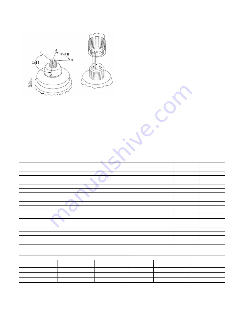
The EXV motor winding resistance can be checked by removal
of the EXV plug. The resistance across coil I should be
52 Ohm (
10%) and the resistance across coil II should be
52 Ohm (
10%). See Fig. 42.
Fig. 42 — EXV Coil Check
Condenser Level
Float level is measured by 0-5V proportional float sensor. Float
sensor is located inside float level sensor housing (Fig. 4). Con-
denser sub-cooler liquid level can also be verified through the
sightglasses on the outboard side of the condenser. The resistance
across the sensor red (vdc) and black (ground) wire should read
approximately 1650 ohm in unpowered state. The sensor voltage
output between white (output) and black (ground) wire is propor-
tional to red-black voltage depending on float location on stem.
High Altitude Locations
Because the chiller is initially calibrated at sea level, it is neces-
sary to recalibrate the pressure transducers if the chiller has been
moved to a high altitude location. Note that Atmospheric Pres-
sure can be adjusted in the Service Parameters Menu (located in
the Configuration Menu).
Quick Test and 19MV Quick Test
The Quick Test feature is located in the Main Menu. Use this fea-
ture to test chiller status, test the status of various actuators, view
water temperature deltas, and test pump and relays, as well as
EXCSV (expansion control system valve), alarms, condenser, and
chilled water pumps. The tests can help to determine whether a
switch is defective or a pump relay is not operating, as well as oth-
er useful troubleshooting issues.
Quick Calibration
Use this menu to calibrate IGVs and EXCSV valve.
End of Life and Equipment Disposal
This equipment has an average design life span of 25 years and
is constructed of primarily steel and copper. Content of control
panels includes but is not limited to common electrical compo-
nents such as fuses, starters, circuit breakers, wire, capacitors
and printed circuit boards. Prior to disposal it will be necessary
to remove all fluids such as water, refrigerant, and oil (if applica-
ble) using the current industry guidelines for recovery/disposal.
In addition electrical components may need to be collected for
recovery and recycling as per local directives.
Physical Data
Tables 22-27 and Fig. 43-49 provide additional information on
component weights, compressor fits and clearances, physical and
electrical data, and wiring schematics for the operator’s conve-
nience during troubleshooting.
* Total compressor weight is the sum of the compressor aerodynamic
components (compressor weight column), stator, rotor, and end bell
cover weights.
† Compressor aerodynamic component weight only, motor weight not
included. Applicable to standard compressors only.
Table 22 — Component Weights
STANDARD COMPONENTS
kg
lb
SUCTION PIPE ASSEMBLY (INCLUDES FLANGES)
110
243
INTERSTAGE PIPING (FROM FLANGE TO FLANGE)
134
295
DISCHARGE PIPING
43
94
NON-ECONOMIZED SYSTEM COPPER TUBING
150
331
HMI PANEL
22
48
POWER PANEL
241
531
DANFOSS D2H VFD
126
277
DANFOSS E1H VFD
295
650
DANFOSS E2H VFD
318
701
VFD CABLE
50
110
VFD CABLE TRAY
124
273
WIRING
20
44
RELIEF VALVE
18
40
EXPANSION CONTROL VALVE
19
42
OPTIONAL COMPONENTS
kg
lb
ECONOMIZER BYPASS AND VALVE
217
478
ISOLATION VALVE
100
220
Table 23 — 19MV Compressor and Motor Weights*
MOTOR
CODE
ENGLISH
SI
Compressor
Weight
†
(lb)
Stator and
Housing Weight (lb)
Rotor and Shaft
Weight (lb)
Compressor
Weight
†
(kg)
Stator and
Housing Weight (kg)
Rotor and Shaft
Weight (kg)
3
2674
963
148
1213
437
67
5
2674
1073
148
1213
487
67
7
2674
1184
148
1213
537
67
Содержание AquaEdge 19MV
Страница 49: ...49 Fig 46 SIOB...
Страница 50: ...50 Fig 47 IOB2...
Страница 51: ...51 Fig 48 19MV Auxiliary Controls Wiring...
Страница 52: ...52 Fig 49 Motor Bearing Control Board Wiring...


