AGAGC9PNS01B Gas Conversion Kit, Propane to Natural: Installation Instructions
Manufacturer reserves the right to change, at any time, specifications and designs without notice and without obligations.
11
5. Install the remaining manifold mounting screws.
6. Connect the wires to the flame sensor and hot surface igniter.
7. Connect the connector harness to gas valve.
NOTE:
Do not use PTFE thread-seal tape.
8. Insert the gas pipe through the grommet in the casing. Apply a thin
layer of pipe dope to the threads of the pipe and thread the pipe by
into the gas valve.
NOTE:
Use a back-up wrench on the gas valve to prevent the valve
from rotating on the manifold or damaging the mounting to the burner
box.
9. With a back-up wrench on the inlet boss of the gas valve, finish
tightening the gas pipe to the gas valve.
10. Turn gas on at electric switch on gas valve.
CHECK INLET GAS PRESSURE
NOTE:
This kit is to be used only when inlet gas pressure is between
4.5-in. w.c. and 13.6-in. w.c.
1. On some models, remove 1/8-in. (3 mm) pipe plug from inlet
pressure tap (see
) and insert pressure tap. Or, on
some models, loosen set screw on inlet tower pressure tap no more
than one full turn with the 3/32-in. hex wrench, see
.
2. Verify manometer is connected to inlet pressure tap on gas valve,
see
.
3. Turn on furnace power supply.
4. Turn gas supply manual shutoff valve to ON position.
5. Turn furnace gas valve switch to ON position.
Single Stage Gas Valve
A190022
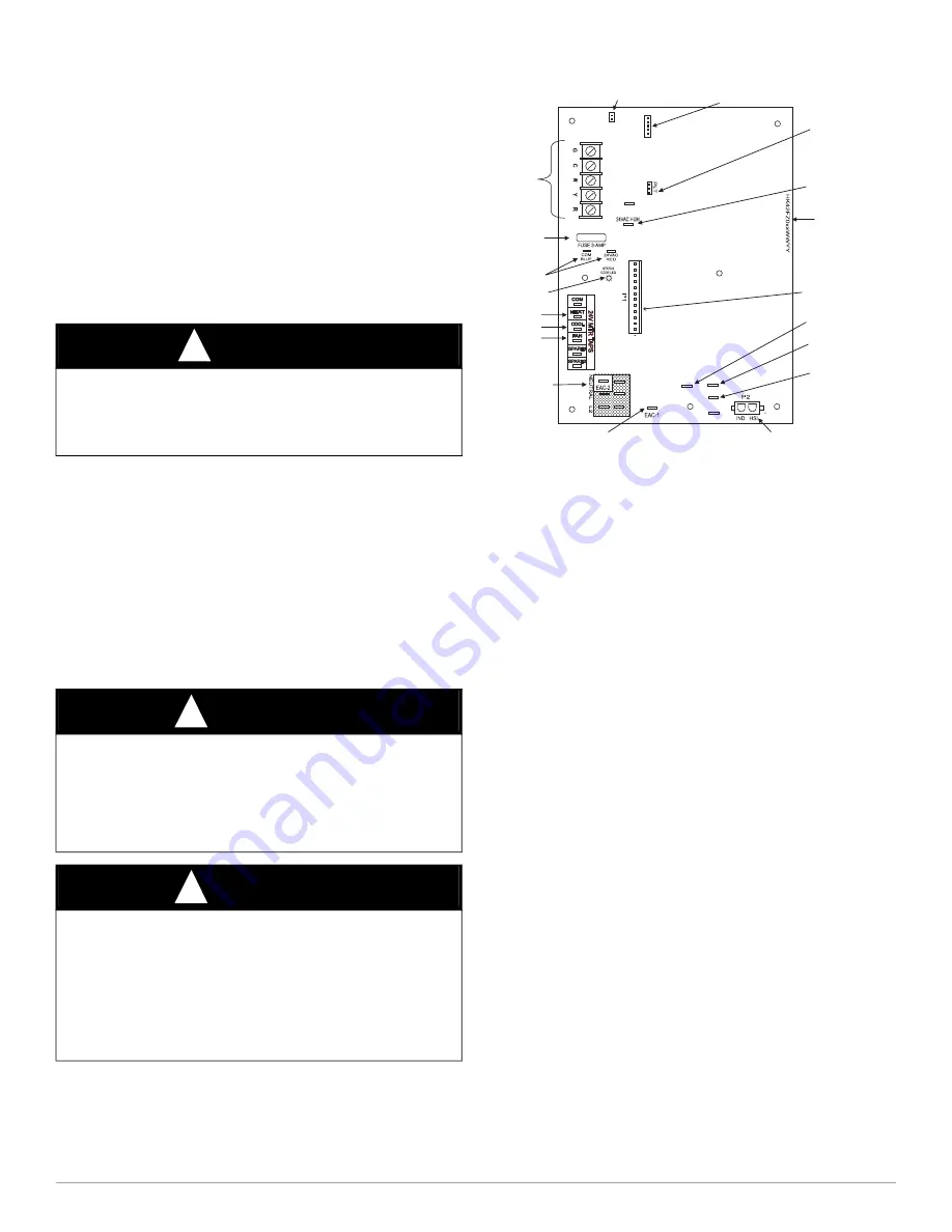
Fig. 20 – Example of Single Stage Furnace Control
1. Jumper R-W thermostat connections on control.
2. When main burners ignite, confirm inlet gas pressure is between
4.5-in. w.c. and 13.6-in. w.c.
3. Remove jumper across R-W thermostat connections to terminate
call for heat.
4. Turn furnace gas valve switch to OFF position.
5. Turn gas supply manual shutoff valve to OFF position.
6. Turn off furnace power supply.
7. Remove manometer and on some models remove pressure tap
fitting.
8. On some models, apply pipe dope sparingly to end of inlet gas pipe
plug and install into unused end of 1/8-in. (3 mm) tee. Use a small
back-up wrench on tee when tightening gas inlet pipe plug. Or, on
some models, tighten set screw on inlet tower pressure tap with a
3/32-in. hex wrench, see
CAUTION
!
UNIT DAMAGE HAZARD
Failure to follow this caution may result in unit damage.
DO NOT operate furnace more than one minute to check inlet gas
pressure, as conversion is not complete at this time.
WARNING
!
FIRE, EXPLOSION, ELECTRICAL SHOCK
HAZARD
Failure to follow this warning could result in personal injury, death or
property damage.
Gas supply MUST be shut off before disconnecting electrical power
and proceeding with conversion.
WARNING
!
ELECTRICAL SHOCK, FIRE OR EXPLOSION HAZARD
Failure to follow this warning could result in personal injury, death or
property damage.
Before installing, modifying, or servicing system, main electrical
disconnect switch must be in the OFF position and install a lockout tag.
There may be more than one disconnect switch. Lock out and tag
switch with a suitable warning label. Verify proper operation after
servicing.
24-V THERMOSTAT
TERMINALS
P2
–
(115VAC) HOT SURFACE IGNITER &
INDUCER MOTOR 115V SUPPLY CONNECTOR
115-VAC (L2) NEUTRAL
CONNECTIONS
115-VAC (BL-1) BLOWER MOTOR LINE
VOLTAGE CONNECTION
EAC-1 TERMINAL
(115-VAC 1.0 AMP MAX.)
P1
–
LOW VOLTAGE MAIN HARNESS
CONNECTOR
TRANSFORMER 24-VAC
CONNECTIONS
3-AMP FUSE
STATUS LED LIGHT
HEAT OFF-DELAY
HUMIDIFIER TERMINAL
(24-VAC 0.5 AMP MAX.)
BOARD PART NUMBER
LOCATION
COOLING SPEED
TAP
HEATING SPEED
TAP
XFMR
115-VAC (PR-1) TRANSFORMER
PRIMARY
J2 DEFEAT
JUMPER
TEST/TWIN
J2
HEAT OFF-DELAY
JUMPER SELECT
L1
PLT -FACTORY RUN TEST PORT
PRODUCTION USE ONLY
BL-1
115-VAC (L1) LINE VOLTAGE
CONNECTION
FAN SPEED TAP
J1
HUM


