


16. Replace burner removal covers on respective sides of furnace.
17. Remove front blower door and reinstall so instructional labels
are rightside up.
NOTE:
On high airflow models (75,000 and 100,000 Btuh), the
front and rear blower doors must be interchanged so that the
instructional labels are rightside up on both sides of furnace. Move
blower door knob to new front blower door.
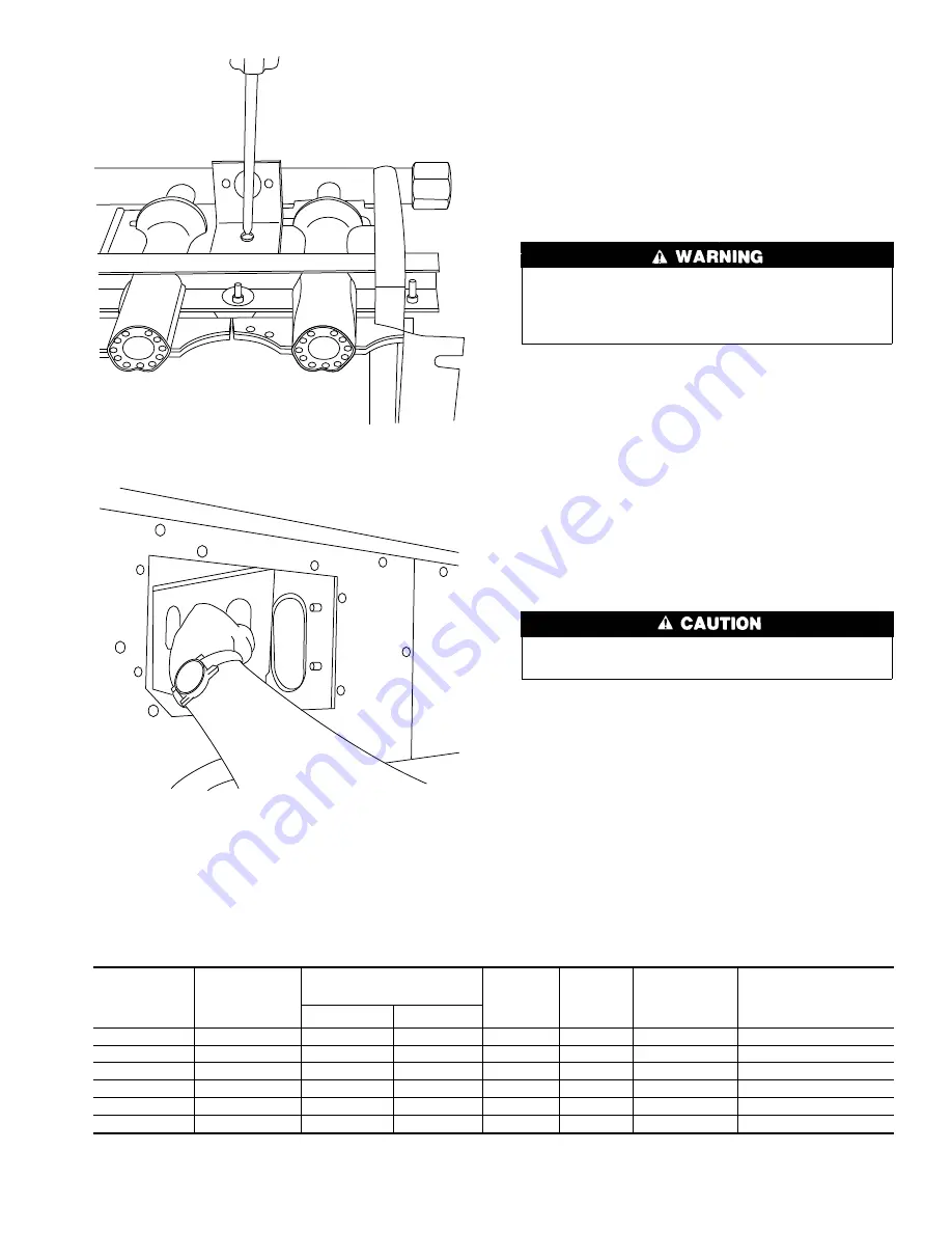
WIRE ALTERNATE LIMIT SWITCH
1. Disconnect wires from limit switch located on front center
panel and reconnect wires to alternate limit switch on right
front panel. (See right-hand view of Fig. 5.)
2. Replace control box cover.
Limit switch wires MUST be moved to the alternate limit
switch when reversing the furnace to ensure safe operation.
Failure to follow this warning may result in a hazardous
operating condition.
ELECTRICAL CONNECTIONS
See Fig. 10 for a wiring diagram showing the proper field 115- and
24-v wiring connections. Check all electrical connections (both
factory and field) for tightness. In all instances, wiring to be done
and any replacement wire shall conform with the temperature
limitation for Type T wire (63°F/35°C rise).
Step 1—115-v Wiring
Before proceeding with electrical connections, make certain that
voltage, frequency, and phase correspond to that specified on unit
rating plate. Also, check to be sure that service provided by utility
is sufficient to handle load imposed by this equipment. Refer to
rating plate or to Table 4 for equipment electrical specifications.
Do not connect aluminum wire between the disconnect switch
and the furnace. Use only copper wire.
Make all electrical connections in accordance with the National
Electric Code ANSI/NFPA 70-1996 and any local codes or
ordinances that might apply.
For Canadian installations, all electrical connections must be made
in accordance with CSA C22.1 Canadian Electrical Code, or
authorities having jurisdiction.
When replacing any original wiring, use only 105°C, AWG No. 16
copper wire.
Use a separate, fused branch electrical circuit containing a properly
sized fuse or HACR-type circuit breaker for this furnace. See
Table 4 for wire size and fuse specifications. A disconnecting
means must be located within sight of and readily accessible to the
furnace.
Table 4—Electrical Data
UNIT SIZE
VOLTS—
HERTZ—
PHASE
OPERATING
VOLTAGE RANGE
MAX
UNIT
AMPS
MIN
WIRE
SIZE
MAX WIRE
LENGTH†
(FT)
MAX FUSE‡ OR
HACR-TYPE
CIRCUIT BREAKER
AMPS
Max*
Min*
050-12
115—60—1
127
104
9.3
14
30
15
075-12
115—60—1
127
104
9.9
14
28
15
075-16
115—60—1
127
104
11.7
12
38
20
100-16
115—60—1
127
104
9.9
14
28
15
100-20
115—60—1
127
104
13.1
12
34
20
125-20
115—60—1
127
104
11.7
12
38
20
* Permissible limits of the voltage range at which the unit will operate satisfactorily.
† Length shown is as measured 1 way along wire path between unit and service panel for maximum 2 percent voltage drop.
‡ Time-delay fuse is recommended.
Fig. 8—Reattaching Rollout Switch Bracket
A96074
Fig. 9—Reversing Burner Opening Inlet Plate
A96075
9