


Step 6—Reversing Procedure
Before proceeding with field reversal, ensure that all electri-
cal power is turned off and that all gas piping is shut off and
disconnected from the furnace. Failure to do so could result in
an extremely hazardous condition and bodily harm.
This furnace may be field reversed allowing for a horizontal right
configuration (left-to-right airflow) instead of the factory posi-
tioned horizontal left configuration (right-to-left airflow). (See Fig.
5.) Field reversal is accomplished in a convenient 3-step process.
1. Invert furnace so top panel is down.
2. Adjust manifold and burner opening plate.
3. Wire alternate limit switch.
INVERT THE FURNACE
1. Carefully flip furnace on its top panel. Care should be taken
not to drop unit or let it rest on 1 of its ends.
2. Controls should now appear as in right-hand view of Fig. 5.
ADJUST MANIFOLD AND BURNER OPENING PLATE
1. Remove front and back burner removal covers located on front
and rear center panels.
2. Cut wire tie securing violet-colored rollout switch wires and
ignition wire to manifold assembly.
3. Disconnect all wires from gas valve.
Label all wires prior to disconnection when servicing con-
trols. Wiring errors can cause improper and dangerous
operation.
4. Remove both manifold retention places from burner box and
remove
burner/manifold
assembly.
While
removing
burner/manifold assembly, disconnect violet-colored rollout
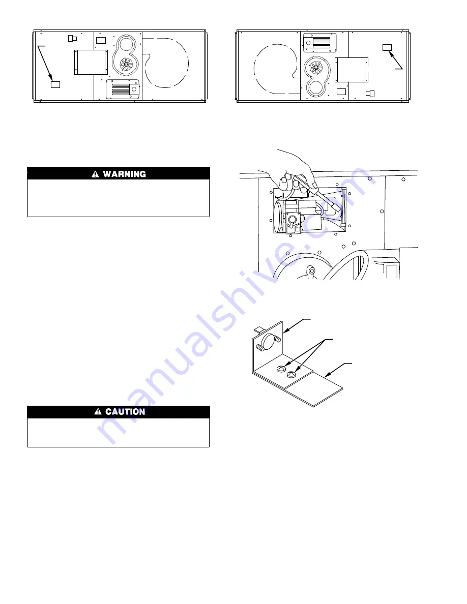
switch wires from rollout switch. (See Fig. 6.)
5. On burner/manifold assembly, remove 2 screws that fasten
rollout switch bracket to rollout switch base bracket. (See Fig.
7.)
6. With
rollout
switch
base
bracket
still
attached
to
burner/manifold assembly, turn assembly over so that pilot
burner is on top.
7. Place rollout switch bracket on rollout switch base so face of
switch is oriented toward heat exchanger.
8. Fasten bracket to base with screws removed in item 5. (See
Fig. 8.)
9. Remove burner opening inlet plate from inside burner box and
reinstall in burner box with word TOP (stamped on part) in up
position. (See Fig. 9.)
10. Replace manifold retention plate on side of furnace opposite
controls.
11. Before installing manifold, reconnect violet-colored rollout
switch wires to rollout switch.
12. Install burner/manifold assembly making sure manifold
bracket slides under manifold retention plate.
13. Install manifold retention plate nearest gas valve. The
burner/manifold assembly should now be firmly attached to
furnace.
14. Reconnect wires to gas valve. Refer to furnace wiring dia-
gram.
15. Secure gas valve wires to manifold assembly with wire tie.
Fig. 5—Control Layout for Reversal
A91387
ALTERNATE
LIMIT
SWITCH
BLOWER
DOOR
CONTROL LAYOUT (AS SHIPPED)
ALTERNATE
LIMIT
SWITCH
BLOWER
DOOR
CONTROL LAYOUT (FIELD REVERSED)
Fig. 6—Removing Burner/Manifold Assembly
A96073
Fig. 7—Rollout Switch Assembly
A92306
SWITCH BRACKET
REMOVE
BASE BRACKET
8