1
QUALITY ASSURANCESYSTEM
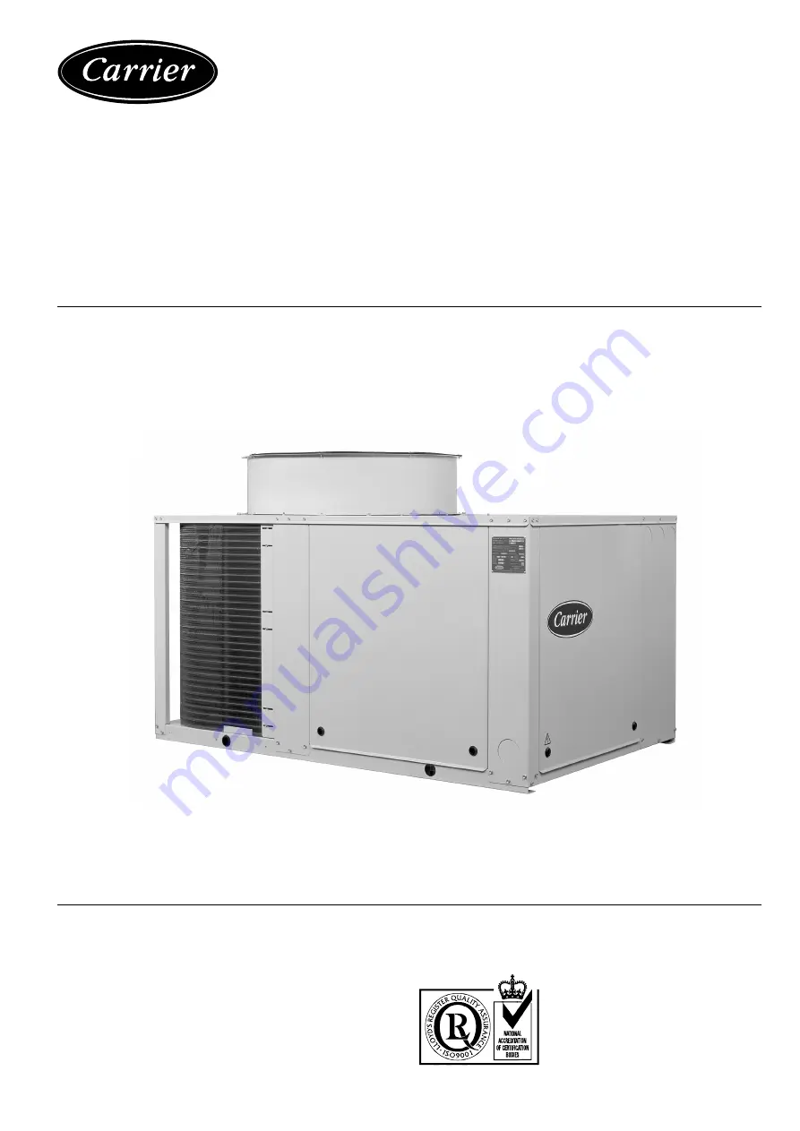
38AJ 008-074 (R-22)38AZ 008-074 (R-407C)Air-Cooled Condensing Units
50 Hz
Installation, Operation and Maintenance Instructions
Страница 1: ...1 QUALITY ASSURANCE SYSTEM 38AJ 008 074 R 22 38AZ 008 074 R 407C Air Cooled Condensing Units 50 Hz Installation Operation and Maintenance Instructions...
Страница 2: ...trol systems 11 Pressure operated control valve 11 Control setpoint 11 Setpoint control 11 Pressure differential 12 Modifications 12 Servicing refrigeration components 13 General maintenance 13 Liquid...
Страница 3: ...gas pressure kPa Pressure drop air kPa Circuit 2 Suction gas temperature C Discharge air pressure Pa Suction gas pressure kPa Fan speed r s or rpm Fan motor input Ph 1 V Ph 2 V Ph 3 V Ph 1 V Ph 2 V P...
Страница 4: ...70 1912 2500 1200 500 1200 062 074 2900 2156 2060 2500 1200 500 1200 Legend All dimensions are given in mm Required clearance space for servicing Power supply Water inlet Water outlet Do not obstruct...
Страница 5: ...unit These units are designed for outdoor installation CAUTION Ensure the air flow around the unit is not obstructed At least two sides of the units must be free from obstructions to ensure proper ai...
Страница 6: ...n dew point temperature R 407C of 10 C saturated discharge temperature R 22 or discharge dew point temperature of 68 3 C ICF maximum instantaneous current during starting equal to the current value of...
Страница 7: ...unit Moving Do not remove skids pallets or protective packaging until the unit is in its final position Move the chiller using tubes or rollers or lift it using slings of the correct capacity Siting B...
Страница 8: ...sure Legend 1 Condenser 2 Liquid line valve 3 Filter drier 4 Sight glass 5 Fan cycling pressure switch 6 Suction valve NOTE The typical refrigeration circuit diagram shown does not apply to all contro...
Страница 9: ...tions to accomplish this Bypass hot gas if used should be introduced before the evaporator Consult your local Carrier distributor The oil charge must be adjusted to allow for extra line length This is...
Страница 10: ...tions use the piping shown for the upper and the middle sections 3 The lower section is always the first section to be activated and the last to be shut off 4 Refer to the Carrier System Design Manual...
Страница 11: ...ergized when the unit is switched off to ensure proper lubrication of the compressor Open the compressor suction and discharge line valves and then close them one turn each to stabilise the pressure t...
Страница 12: ...Pressure operated control valve Modifications It is possible to convert pressure controlled capacity reductions to electrically controlled reductions or to add capacity reductions in accordance with t...
Страница 13: ...es Refrigeration installations must be inspected and maintained regularly and rigorously by specialists Their activities must be overseen and checked by properly trained people To minimise discharge t...
Страница 14: ...hen to ON NOTE Damage resulting from failure to follow these instruction is not covered by the product warranty Compressor motor protection Compressor protection devices Circuit breaker Calibrated the...
Страница 15: ...y removed through the top of the unit Take care not to damage the propeller Label the wires to facilitate correct reassembly later 38AJ AZ 008 012 fan Maximum clearance 80 mm mm 0 2 Maximum clearance...
Страница 16: ...strainer Check valve plates for valve noise Replace compressor worn bearings Check for loose compressor hold down bolts Find and repair leak pump down and recharge Replace heaters check wiring Adjust...