


62-11785
8–28
8.8
ELECTRICAL SYSTEM COMPONENTSERVICE
8.8.1
Main Microprocessor Module (MM)
For complete Main Microprocessor Module replacement instructions refer to
.
8.8.2
Power Control Module (PCM)
NOTE
The buzzer, buzzer harness, fuses, door, door
seal, hinge pin, door screw (with retainer) and
relays may be purchased separately and do
not require complete module replacement.
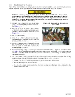
1. Ensure unit will not start automatically by plac-
ing the START/RUN-OFF switch in the OFF
position and removing the battery cables. Dis-
connect the high voltage source and lockout/
tagout the receptacle.
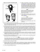
2. Open Power Control module door. Loosen &
remove stud-post terminal nuts (brass) at
terminals BAT+ (6),
); BAT- (5); &
ALT+ (4).
3. Remove nuts holding plastic bushing (3) & leave
hanging on wire.
4. Lift the 4 cable terminals up & off stud-posts.
Remove loose nuts, slide plastic bushings &
cables/terminals out of mounting hole in box.
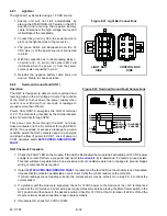
5. Unlock tab on 35 pin connector (2) & remove
connector.
6. Remove the four fasteners (1) mounting Power
Control module to unit frame & remove module
from unit
7. Follow steps above in reverse order to install new
Power Control Module. Torque:
• fasteners mounting module to frame (1) to 38
to 58 inch/lbs (4.3 to 6.6 Nm)
• M6 terminal nut (6) to 30 to 40 inch/lbs
(3.4 to 4.5 Nm)
• M8 terminal nuts (4 & 5) to 60 to 80 inch/lbs
(6.8 to 9.0 Nm). See
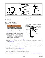
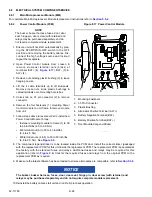
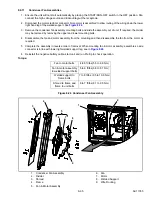
Figure 8.17 Power Control Module
1. Mounting Fasteners
2. 35 Pin Connector
3. Plastic Bushing
4. Alternator Positive Terminal (ALT +)
5. Battery Negative Terminal (BAT-)
6. Battery Positive Terminal (BAT +)
7. Door Mounted Legend Sticker
- - - - -
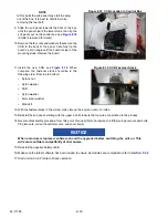
8. The component legend sticker is to be located inside the PCM door. Install the correct sticker (packaged
with the replacement PCM) for this unit inside the replacement PCM. The replacement PCM is populated at
the factory with the standard fuses and relays. Additional fuses and relays may be required for this
application (refer to
) transfer the required fuses and relays from the original PCM to the
replacement PCM as required.
9. Make sure the latest software has been loaded to ensure all modules are compatible, refer to
NOTICE
The buzzer, buzzer harness, fuses, door, door seal, hinge pin, door screw (with retainer) and
relays may be purchased separately and do not require complete module replacement.
10. Reinstall the battery cables, start unit and run Pretrip to check operation.
Содержание VECTOR 8100
Страница 2: ......
Страница 4: ......
Страница 12: ...62 11785 viii ...
Страница 16: ...62 11640 12 ...
Страница 18: ...62 11785 ...
Страница 24: ...62 11785 1 6 1 3 SAFETY DECALS ...
Страница 25: ...1 7 62 11785 ...
Страница 26: ...62 11785 1 8 ...
Страница 27: ...1 9 62 11785 ...
Страница 28: ...62 11785 1 10 ...
Страница 30: ...62 11785 ...
Страница 50: ...62 11785 ...
Страница 82: ...62 11785 ...
Страница 96: ...62 11785 4 14 ...
Страница 98: ...62 11785 ...
Страница 129: ...5 31 62 11785 ...
Страница 130: ...62 11785 5 32 ...
Страница 134: ...62 11785 6 4 ...
Страница 138: ...62 11785 ...
Страница 230: ...62 11785 ...
Страница 271: ...8 41 62 11785 ...
Страница 272: ...62 11785 8 42 ...
Страница 274: ...62 11785 ...
Страница 286: ......
Страница 287: ......
Страница 288: ...62 11785 10 8 ...
Страница 292: ......
Страница 293: ......