


7–45
T-372
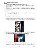
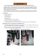
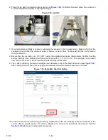
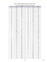
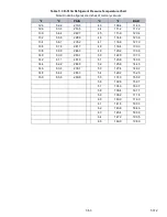
13. Position sensor in unit as shown in
and re-check sensor resistance:
14. Reinstall sensor. Refer to:
- For STS and SRS Reinstallation
- For RRS and RTS Reinstallation
- For DTS Reinstallation
- For ETS1 and ETS2 Reinstallation
NOTE
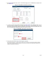
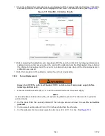
The P5 Pre-Trip test must be run to deactivate probe alarms (see
).
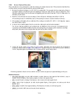
7.28.5
Sensor STS and SRS Reinstallation
To properly position a unit supply sensor (Supply Temperature Sensor STS or Supply Recorder Sensor SRS), the
sensor must be fully inserted into the probe holder. This positioning will give the sensor the optimum amount of expo
-
sure to the supply air stream, and will allow the Controller to operate correctly. Insufficient probe insertion into the
probe holder will result in poor temperature control due to the lack of air flow over the sensor.
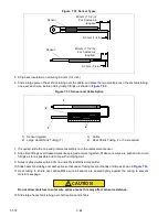
It is also necessary to ensure that the probe tip does not contact the back panel. The design minimum clearance of
6 mm (1/4 inch) should be maintained (see
).
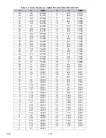
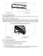
Figure 7.34 Supply Sensor Positioning
1) Sensor Wire
2) Cap & Grommet Assembly
3) Probe Holder
4) Evaporator Back Panel
5) Supply Sensor
- - - - -
7.28.6
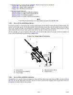
Sensor RTS and RRS Reinstallation
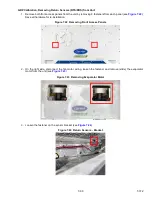
Reinstall the return sensor (Return Temperature Sensor RTS or Return Recorder Sensor RRS), as shown in
. For proper placement of the return sensor, be sure to position the enlarged positioning section of the sen
-
sor against the side of the mounting clamp.
1
2
4
Supply Air
Stream
3
5
6mm (1/4”)
Содержание PrimeLINE 69NT40-571-001
Страница 2: ......
Страница 4: ......
Страница 14: ......
Страница 36: ......
Страница 110: ......
Страница 116: ......
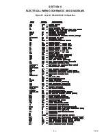
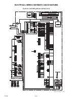
Страница 171: ...8 1 T 372 SECTION 8 ELECTRICAL WIRING SCHEMATIC AND DIAGRAMS Figure 8 1 Legend Standard Unit Configuration ...
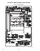
Страница 172: ...T 372 8 2 ELECTRICAL WIRING SCHEMATIC AND DIAGRAMS Figure 8 2 Schematic Diagram Based on Drawing 62 11957 ...
Страница 176: ......
Страница 178: ......
Страница 180: ......
Страница 184: ......
Страница 185: ......