
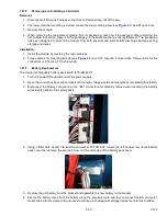


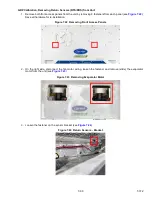


Figure 7.35 Return Sensor Positioning
1) Mounting Clamp
2) Return Sensor
- - - - -
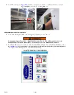
7.28.7
Sensor DTS Reinstallation
The Defrost Temperature Sensor (DTS) must have insulating material placed completely over the sensor to ensure
the coil metal temperature is sensed.
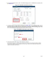
7.28.8
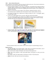
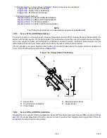
Sensor ETS1 and ETS2 Reinstallation
The Evaporator Temperature Sensors, ETS1 and ETS2 are located in a tube holder under insulation, as illustrated
in
. When the combo sensor is removed and reinstalled, it must be placed in a tube holder by applying
thermal grease. Insulating material must completely cover the sensor to ensure the correct temperature is sensed.
Figure 7.36 Evaporator Temperature Sensor Positioning
1) Insulation
2) ETS Tube Holder
3) ETS1 and ETS2
4) Wire Tie
- - - - -
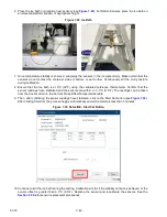
7.28.9
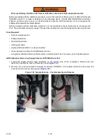
Sensor, CPDS Reinstallation
To replace the Compressor Discharge Temperature Sensor, see
.
1. Ensure the unit is disconnected from the power source.
2. Verify that the Start-Stop switch (ST) is in the “0” position.
3. Remove the existing sensor.
4. Clean all silicone sealer and dielectric compound from the sensor well. Make sure that the well is clean and
dry. The top of the compressor, where the sensor seals, must also be clean and dry.
1
2
1.5 in (38.1 cm)
1
2
3
4
1 .0 ”
25.4cm
Содержание PrimeLINE 69NT40-571-001
Страница 2: ......
Страница 4: ......
Страница 14: ......
Страница 36: ......
Страница 110: ......
Страница 116: ......
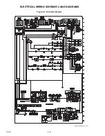
Страница 171: ...8 1 T 372 SECTION 8 ELECTRICAL WIRING SCHEMATIC AND DIAGRAMS Figure 8 1 Legend Standard Unit Configuration ...
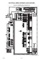
Страница 172: ...T 372 8 2 ELECTRICAL WIRING SCHEMATIC AND DIAGRAMS Figure 8 2 Schematic Diagram Based on Drawing 62 11957 ...
Страница 176: ......
Страница 178: ......
Страница 180: ......
Страница 184: ......
Страница 185: ......