


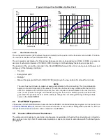


T-372
5–4
5.5.1
Water-Cooled Condenser with Water Pressure Switch
1. Connect the water supply line to the inlet side of the condenser and the discharge line to the outlet side of
the condenser (see
).
2. Maintain a flow rate of 11 to 26 liters per minute (3 to 7 gallons per minute). The water pressure switch will
open to de-energize the condenser fan relay. The condenser fan motor will stop and will remain stopped
until the water pressure switch closes.
3. To shift to air-cooled condenser operation, disconnect the water supply and the discharge line to the water
-
cooled condenser. The refrigeration unit will shift to air-cooled condenser operation when the water pressure
switch closes.
5.5.2
Water-Cooled Condenser with Condenser Fan Switch
1. Connect the water supply line to the inlet side of condenser and the discharge line to the outlet side of the
condenser (see
).
2. Maintain a flow rate of 11 to 26 lpm (3 to 7 gpm).
3. Set the condenser fan switch to position “O.” This will de-energize the condenser fan relay. The condenser
fan motor will stop and remain stopped until the CFS switch is set to position “I.”
CAUTION
!
When condenser water flow is below 11 lpm (3 gpm) or when water-cooled operation is not in
use, the CFS switch MUST be set to position “1” or the unit will not operate properly.
4. To shift to air-cooled condenser operation, stop the unit, set the CFS switch to position “I” and restart the
unit. Disconnect the water lines to the water-cooled condenser.
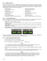
5.6 Starting and Stopping Instructions
WARNING
!
Make sure that the unit circuit breaker(s) CB-1 & CB-2 and the Start-Stop switch (ST) are in the
“O” (OFF) position before connecting to any electrical power source.
NOTE
The electronic phase detection system will check for proper compressor rotation within the first 30 sec
-
onds. If rotation is not correct, the compressor will be stopped and restarted in the opposite direction. If
the compressor is producing unusually loud and continuous noise after the first 30 seconds of operation,
stop the unit and investigate.
5.6.1
Starting the Unit
1. Verify that power is properly applied, the fresh air vent is in proper position, and (if required) the water-
cooled condenser is connected.
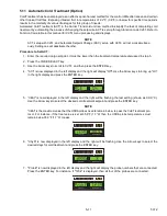
2. Place the Start-Stop switch (ST) to position “I” (ON) (see
). The controller function codes for the
container ID (Cd40), software version (Cd18) and unit model number (Cd20) will be displayed in sequence.
3. Continue with the Start Up Inspection. See
.
5.6.2
Stopping the Unit
1. To stop the unit, place the Start-Stop switch (ST) in position “0” (OFF).
5.7 Start-Up Inspection
5.7.1
Physical Inspection
Check rotation of the condenser and evaporator fans.
5.7.2
Check Controller Function Codes
Check, and if required, reset controller Function Codes (Cd27 through Cd39) in accordance with desired operating
.
Содержание PrimeLINE 69NT40-571-001
Страница 2: ......
Страница 4: ......
Страница 14: ......
Страница 36: ......
Страница 110: ......
Страница 116: ......
Страница 171: ...8 1 T 372 SECTION 8 ELECTRICAL WIRING SCHEMATIC AND DIAGRAMS Figure 8 1 Legend Standard Unit Configuration ...
Страница 172: ...T 372 8 2 ELECTRICAL WIRING SCHEMATIC AND DIAGRAMS Figure 8 2 Schematic Diagram Based on Drawing 62 11957 ...
Страница 176: ......
Страница 178: ......
Страница 180: ......
Страница 184: ......
Страница 185: ......