


T-372
3–6
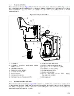
3.1.7
Control Box Section
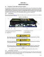
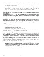
The control box (see
) includes: the manual operation switches, circuit breaker (CB-1), compressor, fan
and heater contactors, control power transformer, transformer AC line filter, fuses, keypad, display module, current
sensor module, and the controller module.
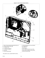
Figure 3.6 Control Box Section
1) Compressor Contactor (CH)
2) Compressor Phase A Contactor (PA)
3) Compressor Phase B Contactor (PB)
4) Heater Contactor (HR)
5) Condenser Fan Contactor (CF)
6) Low Speed Evaporator Fan Contactor (ES)
7) High Speed Evaporator Fan Contactor (EF)
8) Current Sensor Module
9) Circuit Breaker (CB1) 460V
10) Control Transformer
11) Transformer AC Line Filter
12) Start-Stop Switch (ST)
13) Controller / DataCORDER Module
14) Controller Battery Pack and Battery
- - - - -
Содержание PrimeLINE 69NT40-571-001
Страница 2: ......
Страница 4: ......
Страница 14: ......
Страница 36: ......
Страница 110: ......
Страница 116: ......
Страница 171: ...8 1 T 372 SECTION 8 ELECTRICAL WIRING SCHEMATIC AND DIAGRAMS Figure 8 1 Legend Standard Unit Configuration ...
Страница 172: ...T 372 8 2 ELECTRICAL WIRING SCHEMATIC AND DIAGRAMS Figure 8 2 Schematic Diagram Based on Drawing 62 11957 ...
Страница 176: ......
Страница 178: ......
Страница 180: ......
Страница 184: ......
Страница 185: ......