background image

3

NOTE

:  See Winter Start Control Kit for detailed Installation

Instruction.

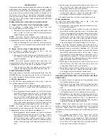
SERVICE FITTING CAP

VALVE CORE END

ADAPTER TEE

FLARE NUT

ON PRESSURE

SWITCH

LIQUID REFRIGERANT SERVICE

VALVE SERVICE FITTING

EXTENDER TUBE

FLARE NUT

A00025

Fig. 1

 — 

Low Ambient Pressure Switch

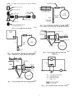
CONNECTOR

CONTACTOR

BLUE

BLACK

FAN

MOTOR

PRESSURE

SWITCH

YELLOW

OR

VIOLET

A97326

Fig. 2

 — 

Power Wiring for All Voltages of Cooling Applica-

tions 

 Single and Two

Stage Non

Communicating Capable

CONNECTOR

CONTROL

BOARD

BLUE

BLACK

FAN

MOTOR

PRESSURE
SWITCH

YELLOW

OR

VIOLET

ODF

A13042

Fig. 3

 — 

Power Wiring for All Voltages of Cooling Applica-

tions 

 Single and Two

Stage Communicating Capable

DEFROST BOARD
OR CONTROL BOARD

ODF OR OF2

O

C

ISOLATION

RELAY

YELLOW

OR VIOLET 

BLUE

BLACK

FAN MOTOR

PRESSURE

SWITCH

2
1

VIOLET

CONNECTOR

BLACK (Wire provided in Isolation Relay Kit)

Wires provided in
Isolation Relay Kit

A12593

Fig. 4

 — 

Power Wiring for 208/230v Heat Pump

Applications

DEFROST

BOARD

O

C

ISOLATION

RELAY

YELLOW

OR VIOLET

BLUE

OUTDOOR

FAN RELAY

BLACK

FAN MOTOR

PRESSURE

SWITCH

1

3

2
1

CONNECTOR

VIOLET

Wires provided in
Isolation Relay Kit

Wire provided in
Isolation Relay Kit

A12594

Fig. 5

 — 

Power Wiring for 460v Heat Pump Applications

C

TDR

LPS

LPS

C

TDR

T

LOW-PRESSURE SWITCH

CONTACTOR COIL

TIME DELAY RELAY

RELAY COIL

FACTORY WIRING

FIELD WIRING

T

A93165

Fig. 6

 — 

Low Voltage Wiring for Winter Start Control

Содержание KSALA0201R22

Страница 1: ...hazards which will result in severe personal injury or death WARNING signifies hazards which could result in personal injury or death CAUTION is used to identify unsafe practices which may result in minor personal injury or product and property damage NOTE is used to highlight suggestions which will result in enhanced installation reliability or operation WARNING ELECTRICAL SHOCK HAZARD Failure to...

Страница 2: ...ent pressure switch to the male piggy back terminal located at tab 2 of relay 4 Install orange wire provided in isolation relay kit to one side of the relay coil Connect the other side to the O wire coming from defrost board or control board 5 Install black wire provided in isolation relay kit to oppos ite side of the relay coil Connect the other side to the C wire coming from defrost board or con...

Страница 3: ... Cooling Applica tions Single and Two Stage Communicating Capable DEFROST BOARD OR CONTROL BOARD ODF OR OF2 O C ISOLATION RELAY YELLOW OR VIOLET BLUE BLACK FAN MOTOR PRESSURE SWITCH 2 1 VIOLET CONNECTOR BLACK Wire provided in Isolation Relay Kit Wires provided in Isolation Relay Kit A12593 Fig 4 Power Wiring for 208 230v Heat Pump Applications DEFROST BOARD O C ISOLATION RELAY YELLOW OR VIOLET BLU...

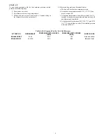
Страница 4: ...s b At outdoor temperatures around 0_F 17 8_C fan may not run at all c At summer temperatures fan will start after 10 to 30 seconds of compressor operation and may not turn off until thermostat is satisfied d At outdoor ambient between 80_F 26 7_C and 20_F 6 7_C fan will turn on and off to maintain pressure as shown in Table 1 Table 1 Kit Usage and Cut In Cut Out Pressures KIT PART NO REFRIGERANT ...

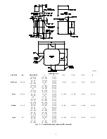
Страница 5: ... 3 4 31 13 16 27 3 16 13 1 2 35 1 4 30 5 8 15 3 16 38 5 8 34 16 7 8 42 37 3 8 18 9 16 45 7 16 40 13 16 20 1 4 Medium 31 1 4 25 1 2 20 3 8 10 1 16 9 3 8 16 5 16 11 9 16 47 3 8 28 15 16 23 13 16 11 3 4 32 5 16 27 3 16 13 1 2 35 3 4 30 5 8 15 3 16 39 1 8 34 16 7 8 42 1 2 37 3 8 18 9 16 45 15 16 40 13 16 20 1 4 Large 35 25 1 2 20 3 8 10 1 16 13 3 16 20 1 8 15 3 8 51 1 8 28 15 16 23 13 16 11 3 4 32 5 1...

Страница 6: ...10 W Morris St S Indianapolis IN 46231 Manufacturer reserves the right to change at any time specifications and designs without notice and without obligations Catalog No IIK KSALA0301 02 Replaces IIK KSALA301 01 Edition Date 01 15 ...

Отзывы: