I N S T R U C T I O N S
For the installation and maintenance of D C 1 5 2 5 - D C 1 5 5 0
d e s u p e r h e a t e r s
IMI0049E.doc
Rev.0 20/08/14
20090 SEGRATE (MI)- via E.Fermi
EMAIL:
TEL.(02) 269912.1 - FAX.(02) 2692.2452
Page 10 of 16
version - 3” (DN 80), with maximum tube schedule of 160; for DC1550 50 m
3
/h version - 4” (DN 100) with
maximum tube schedule of 160.
The minimum length of tube required downstream varies according to application and is specified by
Carraro in the respective quote. This length without bends is necessary to prevent erosion caused by
drops of liquid deposited on the walls of the pipes, the valves and the fittings, and is normally a minimum
of 4, 6 m (a straight length of pipe is not generally necessary upstream). The distance that separates the
desuperheater from the temperature sensor is between 12 and 15 m, although the specific distance for
the application is generally specified in the quote.
Longer distances ensure complete evaporation of the liquid at lower process gas speeds. The
temperature sensor must be located in the top half of the pipe. Avoid fitting branches of the vapour pipe
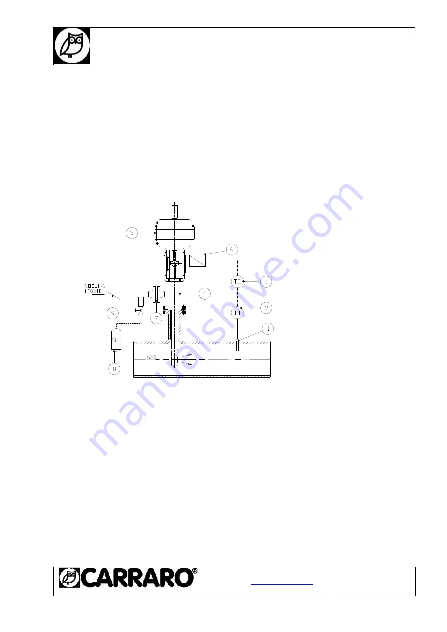
between the desuperheater and the sensor (see Fig. 3).
1) Temperature sensor
2) Temperature transmitter
3) Temperature control
4) Varicryo
5) Actuator
6) Positioner
7) Filter (Optional)
8) Auxiliary N2
9) Check valve
Fig. 3
The unit can be fitted on either horizontal or vertical pipes. The direction of liquid injection must
correspond to the direction of process gas flow. The desuperheater can be fitted at 90° to the vapour
pipe, regardless of direction of flow. The allowed orientations are outlined in Fig. 4. Vertically downwards
position must be achieved If installed horizontally, the unit must be mounted with a weight-compensation
system.


