background image

15

gp

electric.com


GP-RV-80

GP-RV-95

GP-RV-160

GP-RV-80E

GP-RV-95E

GP-RV-160E 

Weekender SW

Weekender HD

Solar Elite

Solar Extreme

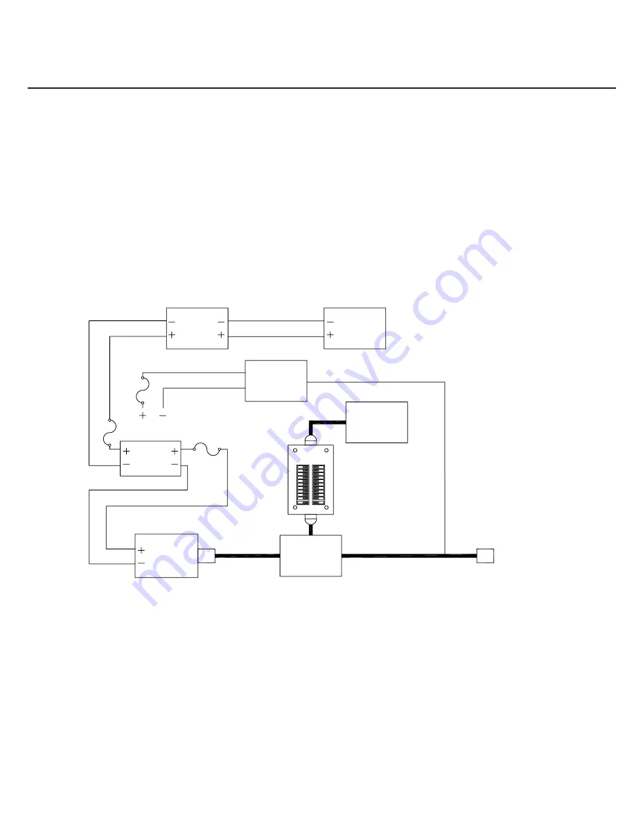
Diagram 6

Inverter

Battery

Solar 

Module

Loads

Charge

Controller

Converter/

Battery 

Charger

Utility Power or 

Generator

AC 

Panel

Transfer 

Switch

Diagram is recommended wiring only. Compliance 

with governing electrical code is assumed.

In no event will Carmanah be liable to any party or 

for any direct, indirect, special or other consequential 

damages resulting from use of this diagram.

If the inverter supplies power to the AC panel which provides 

power to a converter, the resulting battery loop will quickly drain 

the batteries.
Disconnect the converter entirely from the system via a breaker 

or physically disconnecting the wires.
Usually the converter with circuit protection is rewired to connect 

to the utility power side of the system, if utility power is available.

RV Electrical Layout - Two AC Power Sources 

with Automatic Transfer Switch

All positive conductors connected 

to the battery should be equipped 

with the circuit protection rated to 

the wire size used.

Содержание Go Power! GP-RV-160

Страница 1: ...Owner s Manual powered by RV Solar Power Kits GP RV 80 GP RV 95 GP RV 160 Weekender SW Weekender HD Solar Elite Solar Extreme Expansion Kits GP RV 80E GP RV 95E GP RV 160E Solar Extreme shown here ...

Страница 2: ...2 gpelectric com GP RV 80 GP RV 95 GP RV 160 GP RV 80E GP RV 95E GP RV 160E Weekender SW Weekender HD Solar Elite Solar Extreme ...

Страница 3: ...3 2 Solar Elite Multimodule System MC4 Junction Box 5 3 3 Solar Extreme Multimodule System MC4 Junction Box 3 4 GP RV 80E 95E 160E Expanding to a Multimodule System MC4 Junction Box 5 3 5 Modules with MC4 Connectors Wired to a Non Potted Junction Box 5 4 0 Routing Power Cable through the Fridge Vent 6 4 1 Method 1 Hole in Side of Vent 6 4 2 Method 2 Through Screen Grid 6 5 0 Mounting the Solar Mod...

Страница 4: ...le 18 GP PWM Controller 19 ARM UNI Mount Optional 20 10 1 Wood Screws The Solar Elite includes GP SW2000 12 GP SWR B 12 GP DC Kit4 GPC 45 MAX and GP TS The Weekender SW includes GP SW1500 12 GP SW Remote GP DC Kit3 and GP TS The Solar Extreme includes GP SW3000 12 GP SWR B GP DC Kit 5 GPC 75 MAX and GP TS 01 02 03 07 08 09 10 11 12 13 14 16 17 Solar Module GP PWM Controller 18 Parts Checklist Batt...

Страница 5: ...disconnected When modules are connected in parallel amperages are additive Consequently a system assembled from photovoltaic modules can produce high amperages which constitute an increased hazard Do not touch terminals while module is exposed to light Cover the module face completely with opaque material to halt the production of electricity when installing or working with modules or wiring Batte...

Страница 6: ... connector must plug into a positive connector in order to extend it Please remember the polarity of an MC4 cable wire run is the polarity symbol on the connector closest to the MC4 junction box It is advisable to attach a polarity sticker to the positive extension cable in order to avoid confusion 3 1 GP RV 80 95 155 Weekender HD Weekender SW Single Module System MC Junction Box RV Kits containin...

Страница 7: ...e 1 4 bolts washers and nuts as shown in Figure 2 2 Tighten nuts securely using a 7 16 wrench 3 Place the module in a location that follows the criteria listed here Select a location where the mounting surface is at least 1 2 thick and strong enough to support mounting hardware the solar module and wind loads Minimize distance between the location of the solar module and the location where the pow...

Страница 8: ...lected 2 Use the template included in the GP PWM 30 Manual to mark the four mounting holes and the cutting line for flush mounting Drill the mounting holes Use a keyhole or jig saw to cut along the rectangular outline you marked 3 Wire the controller as shown in the GP PWM 30 Manual Use the leftover power cable to connect the controller to the batteries 4 Mount the controller to the wall using the...

Страница 9: ...ead the frequently asked questions section of our website to troubleshoot the problem If trouble persists 1 Call your Go Power Technical Support team 1 866 247 6527 2 Return defective product to place of purchase 8 3 Additional Information Unless approved by Go Power management all product shipped collect to Go Power will be refused Test items or items that are not under warranty or units that are...

Страница 10: ...nnectors of the MC4 junction box If you have more than one module refer to the specific diagram for wiring a parallel MC4 connection 2 Run the positive and negative MC4 cable conductors from the solar array to the solar controller Attach a positive polarity label to the end of the positive conductor If the positive conductor needs to be shortened and the polarity label is removed remember to re la...

Страница 11: ...rallel Connector Female Wiring Parallel 2 Modules with MC4 Parallel Connectors Positive MC4 Parallel Connector Male Note solar module junction box and MC4 cables many not be exactly as shown MC4 Extension Cable to Solar Controller or Combiner Box MC4 Cable Connections for 2 Parallel Modules E G Two 12V modules at 12V MC4 Parallel Male MC4 Parallel Female ...

Страница 12: ...ive MC4 Parallel Connector Female Positive MC4 Parallel Connector Male MC4 Extension Cable MC4 Output 10 Existing MC Power Cable to Solar Controller Parallel Wiring Between a Standard Junction Box and an Existing MC4 Cable Junction Box Note solar module junction box and MC4 cables many not be exactly as shown MC4 Parallel Male MC4 Parallel Female MC4 Extension Cable MC4 Output 10 Existing Power Ca...

Страница 13: ...op will quickly drain the batteries Disconnect the converter entirely from the system via a breaker or physically disconnecting the wires Usually the converter with circuit protection is rewired to connect to the utility power side of the system if utility power is available Diagram is recommended wiring only Compliance with governing electrical code is assumed Shore Power Cable Inverter Battery S...

Страница 14: ...to connect to the utility power side of the system if utility power is available Inverter Battery Solar Module Loads Charge Controller Converter Battery Charger Shore Power Cable In the absence of a transfer switch the AC panel connection is physically unplugged from inverter and plugged into utility power and vice versa Utility Power or Generator Diagram is recommended wiring only Compliance with...

Страница 15: ...or other consequential damages resulting from use of this diagram If the inverter supplies power to the AC panel which provides power to a converter the resulting battery loop will quickly drain the batteries Disconnect the converter entirely from the system via a breaker or physically disconnecting the wires Usually the converter with circuit protection is rewired to connect to the utility power ...

Страница 16: ...c com powered by 2013 GO POWER By Carmanah Technologies MOBI_MAN_GP RV Install Kit and Systems_160 indd GP RV 80 GP RV 95 GP RV 160 GP RV 80E GP RV 95E GP RV 160E Weekender SW Weekender HD Solar Elite Solar Extreme ...

Отзывы: