background image

Owner’s Manual | Model A704-5 Aviation Lighting System 

12 

© 2008 Carmanah Technologies Corporation 

Last revised: April 2008 

Some finer points of button usage include: 


To more quickly cycle through the command levels, try releasing the button briefly 
when each amber flash occurs, and then pressing it down again (e.g. for command 
level 3: hold the button until the amber LED flashes once, then release it briefly and 
hold it down again until the amber LED flashes twice, release briefly and hold down 
until it flashes three times). 

Example: To set the Model A704-5 to Ship Mode, follow these steps: 

1.  Hold the push button down. The amber indicator LED will blink once after approximately two seconds 

and twice after approximately four seconds. 

Release the push button. 

Immediately press the button once. The green LED will blink once to confirm one press. The red LED will 
then briefly flash as the light enters Ship Mode. 

The Model A704-5 is now in Ship Mode. 


In the following sections, shorthand terminology is used to refer to particular push hold 
/ button press sequences in the format: [x, y] specifying hold for x amber flashes, press 
y times followed by y green flashes. For example, [0, 5] is Flash Toggle; [4, 1] is 
Battery Check. [0] = no hold; proceed directly to the press. 

Button Sequence [0, 1]: Standby Mode 

Button sequence [0, 1] puts the Model A704-5 in Standby Mode. This will immediately extinguish the light, 
and the light will resume autonomous operation at its last set Autonomous Output Mode after detecting a 
day-to-night transition. 

If a light is in a Temp Mode and is put into Standby Mode, it reverts to the last programmed Autonomous 
setting (and will turn on in the next day-night transition). 

Button Sequence [0, 2-4]: Autonomous Output Modes 

The Model A704-5 has three Autonomous Output Modes: low, medium, and high intensity. These are the 
standard operating modes for dusk to dawn operation when the light is deployed differing by light 
intensity. The Autonomous Modes operate independently of an external power source as long as local 
sunlight conditions can adequately sustain the battery state of charge. 


If the light is put into an Autonomous Mode during the day or in a bright environment, 
the main LEDs will remain off until the light senses nightfall. If the Model A704-5 is 
programmed to the Autonomous Mode at night or in low-light conditions, the main 
LEDs will be on until daylight is detected. 

Button [0, 5]: Flash Toggle 

The flash toggle setting alternates the light between steady-on or flashing. In Flash Mode, the light 
flashes at once per second (0.3 seconds on, 0.7 seconds off). The three Autonomous Output Modes (low, 
medium and high) can be either steady-on or flashing. 

When in Autonomous Mode, the Model A704-5 may automatically decrease its intensity if it detects that it 
does not have sufficient battery charge to continue autonomous operation at that brightness. When the 
Model A704-5 detects that it is receiving sufficient battery charge to resume autonomous operation at the 
original user setting, it revert to its original intensity. For more information, see section 

4.3.3 Automatic 

Light Control (ALC)

Содержание A704-5

Страница 1: ...Owner s Manual Model A704 5 Wireless Aviation Lighting System ...

Страница 2: ...uide 9 4 3 Programming Options 10 4 3 1 Indicator LEDs 10 4 3 2 Push Button Operation 11 4 3 3 Automatic Light Control ALC 16 4 3 4 24 Hour Shutoff 16 5 0 Wireless Controller Operation 17 5 1 Proper Antenna Orientation 17 5 2 Wireless Controller Quick Start Guide 19 5 3 Wireless Controller Modes 19 5 3 1 User Mode 19 5 3 2 Administrator Mode 20 5 3 3 Mode Selection 20 5 4 PIN Entry 20 5 5 Basic Us...

Страница 3: ...Low Battery Recovery Method 33 7 0 Installing the Model A704 5 Aviation Light 35 7 1 Installation 35 7 2 Optional Airport Mounting Stake 35 7 3 Location 35 8 0 Model A704 5 Operational Maintenance Diagnostics 36 9 0 Maintenance and Product Care 37 9 1 Light Battery Self Discharge During Storage 37 9 2 Charging Model A704 5 Light s Batteries 37 9 3 Model A704 5 AC DC Charger Part 48898 38 10 0 Serv...

Страница 4: ...chnology the Model A704 5 Aviation Lighting System is an advanced portable self contained aviation lighting solution The system is designed to operate reliably under extreme environmental conditions This manual describes the increased functionality of v3 00 firmware released October 2007 Some of the features described in this manual are not available in older systems For your convenience both the ...

Страница 5: ...gienists ACGIH is 65mW in2 10mW cm2 as the maximum exposure limit for viewing for up to 16 minutes This power density can be produced by a Model A704 5 at the lens surface when actively emitting infrared light High power visible spectrum LEDs also pose an eye safety risk if viewed inappropriately Figure 2 1 LED Viewing Precautions 2 2 Battery Precautions Use extreme caution when handling the light...

Страница 6: ...ise in temperature of 16 degrees Fahrenheit the battery storage life is reduced by one half Storage in a cool area under 68 degrees Fahrenheit is recommended Table 2 1 Recharge Intervals Storage Temperature C F Recharge Interval Months 20 or lower 68 or lower 3 20 to 40 68 to 104 1 40 or higher 104 or higher Twice Monthly See section 9 0 Maintenance and Product Care for information on recharging t...

Страница 7: ... April 2008 3 0 Component Identification 3 1 Model A704 5 Light External power connector Antenna connector Handle Push button Indicator LEDs Reflector Optional antenna Top solar panel Side solar panels Main beam LEDs Lens Base plate with mounting holes Figure 3 1 Model A704 5 Light Component Identification ...

Страница 8: ...Lighting System 8 2008 Carmanah Technologies Corporation Last revised April 2008 3 2 Wireless Controller Antenna Communications connector External power connector ARCAL connector Vent Figure 3 2 Wireless Controller Component Identification ...

Страница 9: ...the Model A704 5 will not illuminate until the next nightfall During the day the Model A704 5 charges from sunlight The capacity of the Model A704 5 s battery ensures that even with poor levels of sunlight over extended periods the light has enough reserve power to continue to perform reliably The Model A704 5 is completely power autonomous wiring to an external power supply is not required in mos...

Страница 10: ...There are two options for programming the Model A704 5 light Push Button The black push button on the top of the Model A704 5 allows manual programming of the Model A704 5 features and operation Wireless Controller The wireless controller is capable of performing all push button operations as well as several advanced operations See section 5 0 Wireless Controller Operation 4 3 1 Indicator LEDs Loc...

Страница 11: ...t Table 4 1 Overview of Command Levels and Modes Step 1 Choose Command Level Step 2 Choose Command Action Response Command Level 1 press 1 Green Indicator LED Flash 2 presses 2 Green Indicator LED Flashes 3 presses 3 Green Indicator LED Flashes 4 presses 4 Green Indicator LED Flashes 5 presses 5 Green Indicator LED Flashes No Amber Flash 0 Autonomous Standby Mode2 Autonomous Low Autonomous Med Aut...

Страница 12: ...Autonomous Output Mode after detecting a day to night transition If a light is in a Temp Mode and is put into Standby Mode it reverts to the last programmed Autonomous setting and will turn on in the next day night transition Button Sequence 0 2 4 Autonomous Output Modes The Model A704 5 has three Autonomous Output Modes low medium and high intensity These are the standard operating modes for dusk...

Страница 13: ...ight will remain in a programmed temporary high intensity setting until commanded otherwise or until the light detects that external power is no longer available For more on this see Button Sequence 5 3 Temporary High Intensity Mode Timeout If the wireless handheld controller is used to invoke a temporary High Intensity Mode the lights will remain on for only 15 minutes before resuming their last ...

Страница 14: ...onal infrared LEDs the infrared toggle will have no effect The Model A704 5 will continue to operate in the visible light mode last set When infrared mode is toggled on the Model A704 5 will continue operating in whatever mode it was previously programmed for i e intensity and flash steady on except that it will be emitting infrared instead of visible light The indicator LEDs will not display anyt...

Страница 15: ...t This function toggles on off the Temporary High Intensity Timeout Temp Timeout With the Temp Timeout toggle is on the light always stays on for one hour when placed into a temporary high intensity setting using the pushbutton switch When the Temp Timeout toggle is off and the light senses that it s connected to an active 12V DC source the light will stay on indefinitely when placed into a tempor...

Страница 16: ...d for Temporary High Intensity Modes These thresholds are not to be confused with battery state of charge thresholds Table 4 6 ALC Dimming Levels State of Charge ALC Dimming Level 60 100 100 intensity 50 60 75 intensity 40 50 50 intensity 0 40 25 intensity 4 3 4 24 Hour Shutoff If the Model A704 5 senses ambient light levels of 30 lux or less for 24 consecutive hours it will assume it is being sto...

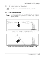
Страница 17: ... Antenna Orientation The effective range of the transmitter is 2 5 miles 4 km for the 1 watt controller and 1 2 miles 2 km for the watt controller depending on the location The antenna s range is most effective when pointed parallel to the light s antenna See the diagrams below for more detail Figure 5 1 Correct Orientation of Controller Antenna to Light Figure 5 2 Incorrect less effective range O...

Страница 18: ...transmission The UCS feature has several benefits 1 Added security in the event that a controller is stolen or lost a new UCS can be configured between the new controller and the lights This prevents the stolen or lost controller from being used by unauthorized persons to control the lights Independent operation nearby installations of lights can be operated independently by different controllers ...

Страница 19: ...ED will turn off to indicate the controller has accepted the PIN and is ready to be used to control A704 5 lights If the PIN is accepted the ENTER key LED will briefly light green and PIN STATUS will turn off or begin to flash depending on whether the User or Administer Mode was selected If the PIN is not accepted the ENTER key LED will briefly light red and the PIN Status red LED will remain lit ...

Страница 20: ...roller by pressing the POWER button To use the wireless controller after turning it on a PIN must be entered the red PIN Status LED turns on steady to indicate this As the PIN is entered the ACTIVE GROUP green LEDs will light to indicate the number of keys pressed Press the ENTER key to submit the PIN The wireless controller factory default PINs are shown in Table 8 Default PINs Table 5 1 Default ...

Страница 21: ...be programmed day or night however they will not turn on in the daytime when programmed in the daytime To turn on the light s in Autonomous Operation Mode Press the AUTO button Press intensity level LOW MED or HIGH Press ENTER A704 5 lights in AUTO Mode located near other lights within 1 foot may turn off due to the light emitted from them 5 6 4 Temporary Operation Mode Lights set to temporary hig...

Страница 22: ...utton turning the IR button LED off Press ENTER 5 6 7 Standby Mode Standby Mode turns off all lights until the next nightfall To go into standby mode Press STANDBY Press ENTER 5 6 8 Lights Off Mode If the lights are placed in Lights Off mode they will not automatically turn on at the next day night transition Lights Off Mode turns off all lights until they are turned on again by the wireless contr...

Страница 23: ...State 5 or less To enter Diagnose Mode on the controller Press DIAGNOSE The DIAGNOSE LED starts flashing Press ENTER The DIAGNOSE LED turns on To send the Diagnose command to the lights Press one of HIGH MED LOW or Lights Off Press ENTER To exit diagnose mode on the controller Press DIAGNOSE The DIAGNOSE LED starts flashing Press ENTER The DIAGNOSE LED turns off 5 7 2 Radio Health Diagnose Functio...

Страница 24: ...ed to another group as required To select one or more groups of lights to control Press SELECT GROUP Press the group number s using the buttons 1 through 8 Press ENTER Commands entered now apply only to the groups indicated by the Active Group LEDs 5 7 4 Configure Groups To configure a subset of lights as a group Enter Configure Mode on the controller Press CONFIG The CONFIG LED starts flashing Pr...

Страница 25: ...ced Administrator Mode operations of the wireless controller The controller must be in Administrator Mode to access any of the features described in this section To place the controller into Administrator Mode Turn on the controller by pressing the CONTROLLER POWER button All buttons flash briefly The green LED on the CONTROLLER POWER button will turn on and the red PIN Status LED will be on stead...

Страница 26: ...er key LED will briefly light green If the PINs do not match or the PIN is the same as the User PIN the Enter key LED will briefly light red and you will need to start again Using the CLEAR key If the CLEAR key is pressed and no PIN digits have been entered the controller will return to Administrator Mode with no Administrator operations selected If the CLEAR key is pressed and at least one PIN di...

Страница 27: ...key LED will light green briefly to indicate a successful operation The controller is now in the Transmit UCS operation and will transmit the UCS every time the ENTER key is pressed Pressing CLEAR will exit the Transmit UCS operation and return the wireless controller to Administrator Mode Remove UCS Operation Place the controller into Administrator Mode Press 0 The 0 LED starts flashing Press ENT...

Страница 28: ...ransmitted from another controller There is no way to retrieve a UCS once it has been removed or overwritten so it is recommended the UCS be transmitted to a backup controller Initialization Both the wireless controller and A704 5 light arrive from the factory with UCS removed Complete the following steps to initialize an airfield with a UCS 1 If not already in Administrator Mode put the controlle...

Страница 29: ... controller into Administrator Mode section 5 4 2 Administrator Mode 2 Generate a new UCS 7 ENTER see section 5 8 3 Unique Code Sequence UCS Management 3 Enter Transmit UCS Mode 9 ENTER see section 5 8 3 Unique Code Sequence UCS Management 4 Transmit the UCS by pressing the ENTER button on the wireless controller see section 5 8 3 Unique Code Sequence UCS Management The A704 5 light s will flash f...

Страница 30: ...8 ENTER see section 5 8 3 Unique Code Sequence UCS Management Unique Code Sequence UCS Management 3 Enter Transmit UCS Mode on controller A 9 ENTER see section 5 8 3 Unique Code Sequence UCS Management Unique Code Sequence UCS Management The ENTER LED on controller B will light briefly to indicate the UCS was received controller B will then exit Receive UCS Mode and return to Administrator Mode 4 ...

Страница 31: ...UCS information if enabled is removed The UCS light returns to its default state which is UCS disabled To perform the Factory Reset 1 Turn the controller off and then turn it on The PIN STATUS red LED will turn on to indicate the controller is ready to receive the password 1 Enter the factory reset code 1223334444 2 Press ENTER All controller LEDs will turn on briefly indicating a successful facto...

Страница 32: ...lect all groups and confirm lights are operating through trial and error The light is unresponsive to radio commands but works via pushbutton The light is encountering radio reset problem Perform the Radio Health Diagnostic section 5 7 2 Radio Health Diagnose Function Install antenna s by tightening firmly by hand If yes no problem The ambient brightness level is above 500 lux Darken the environme...

Страница 33: ...red and green indicator LEDs will light up during the cycle Battery replacement is recommended although some batteries will respond to the following advanced recharge method This is an advanced method and should be carried out by personnel familiar with the equipment outlined below Perform in a room temperature 68 F 20 C environment Required equipment Power supply capable of 10V 5A Custom cable ha...

Страница 34: ... battery If the battery voltage does not reach 10V power supply switching to CV from CC Mode within five hours then the battery is not taking a charge Stop charging and replace the battery If the battery voltage has reached 10V within five hours stop charging and reconnect the battery to the A704 5 You can then top up the battery using the A704 5 external charging adapter When using the external c...

Страница 35: ... to 4 10 16 cm diameter hole to a depth of 30 76 cm Install the top of the stake even with or not more than 1 2 1 3 cm above the finished grade and maintain within 1 degree of the vertical Backfill around the stake with thoroughly compacted earth or suitable backfill material such as sand or concrete For hard bedrock or sediment areas 15 38 1 cm stakes can be used In areas where frost may cause he...

Страница 36: ...TEMP LOW ENTER command from the radio controller All lights should come on in the Temporary Low Mode If it is not obvious then drive or walk the length of the runway to verify operation 4 If any lights fail to respond then repeat Steps 1 3 above If lights still do not respond then refer to section 6 0 Troubleshooting 5 Extinguish the lights by pressing STANDBY ENTER Verify that all lights turn off...

Страница 37: ...nded maximum storage intervals between recharging depending on the temperature of the storage location Table 9 1 Recharge Intervals Storage Temperature o F o C Recharge Interval Months 68 or lower 20 or lower 3 68 to 104 20 to 40 1 104 or higher 40 or higher Twice monthly 9 2 Charging Model A704 5 Light s Batteries Follow one of the charging recommendations outlined in Table 11 Charging Alternativ...

Страница 38: ... the connectors by rotating the collar on the charger plug clockwise The amber LED on the Model A704 5 will flash to indicate that the light s batteries are charging The charger may be left connected to the Model A704 5 Once a full charge is reached the light automatically goes into Trickle Charge Mode to prevent the batteries from overcharging Safety Information Only use the Model A704 5 charger ...

Страница 39: ...uct online Before contacting Carmanah s customer service department please have the serial number of your A704 5 available a brief description of the problem as well as all details of the installation and recharging efforts To contact Carmanah s Customer Service Department Mail Carmanah Technologies Corp Building 4 203 Harbour Road Victoria BC Canada V9A 3S2 Phone 1 250 380 0052 1 877 722 8877 Tol...

Страница 40: ...no guarantee that interference will not occur in a particular installation If this equipment does cause harmful interference to radio or television reception which can be determined by turning the equipment off or on the user is encouraged to try to correct the interference by one or more of the following measures Reorient or relocate the receiving antenna Increase the separation between the equip...

Страница 41: ...charge is too small to be felt Infrared IR The name means below red from the Latin infra below red being the color of visible light of longest wavelength The invisible part of light with longer wavelengths that is felt as heat radiation The invisible heat radiations are beyond the red end on the visible spectrum and cannot be seen by the human eye Light Emitting Diode LED A Light Emitting Diode LE...

Страница 42: ...ease recycle Tools Required Ratchet 1 2 socket with extension 5 32 Hex key 2 Phillips screwdriver Contact Carmanah sales to order toolkits and replacement batteries Battery Replacement Procedure Remove all jewelry including rings and bracelets Bridging battery terminals with any metal could cause high electrical currents and severe burns 1 Use an ESD wrist strap connected to a suitable electrical ...

Страница 43: ... seal may be sticky see Figure 11 2 Figure 11 2 Lifting off the Head 4 Disconnect the main wiring harness from the underside of the head see Figure 11 3 5 Use the pinch points to squeeze the connector then pull it free Do not force the connector as it will pull free easily when the pinch points are properly squeezed Figure 11 3 Wire Harness Disconnection ...

Страница 44: ...008 6 Remove the ground strap from the head using the Phillips screwdriver see Figure 11 4 Do not drop the ground strap retaining screw into the housing Figure 11 4 Removing the Ground Strap 7 Remove the head and set aside 8 Disconnect the battery harness see Figure 11 5 Figure 11 5 Disconnecting the Battery Harness ...

Страница 45: ...ery terminals will create large electrical currents and could cause severe burns Once the bolt is loosened completely carefully remove the bolt and ground strap Figure 11 6 Removing the Battery Retention Bolt 10 Grasp the battery harness by the wires and pull the battery pack straight up out of the main housing see Figure 11 7 Ensure that you grasp the wires rather than just the connector when rem...

Страница 46: ...w battery harness by the wires and lift the new batteries into the main housing 14 Insert the battery retention bolt through the circular terminal of the ground strap and hand tighten the bolt using the socket and extension see Figure 11 9 Figure 11 9 Tightening the Bolt 15 Using the ratchet tighten the battery retention bolt turn at a time After each turn check that the batteries are firmly held ...

Страница 47: ...Figure 11 10 Figure 11 10 Replacing the New Gasket 18 Grasp the head and align the handle with the charge plug on the base of the light While holding the head re attach the ground strap using the screwdriver see Figure 11 11 Do not drop the ground strap retaining screw into the housing 19 Place the head on top of the housing aligning the handle and the charging connector on the base of the light s...

Страница 48: ...r the head onto the main housing Ensure that all wiring on the underside is tucked in the housing and there are no pinched wires Ensure the gasket is seated properly see Figure 11 12 Figure 11 12 Replacing the Head 23 Replace top plate screws and washers and tighten to finger tight 24 Using the hex key tighten the four screws down lightly to ensure the top plate is flat against the housing Next ti...

Страница 49: ...steps 1 Use an ESD wrist strap connected to a suitable electrical ground If one is not available avoid touching any electronics within the enclosure unless required by this process 2 Open the controller lid by removing the four screws in the enclosure corners See Figure 20 Controller Lid Figure 11 13 Controller Lid 3 Unplug the battery and WAIT 3 or 4 MINUTES to allow the capacitors in the circuit...

Страница 50: ...tion Last revised April 2008 Figure 11 15 Battery Connector Final Position 5 Replace the controller lid tightening the four screws firmly 6 Connect the AC DC charger the controller battery LEDs should cycle 7 Leave the controller connected to the AC DC charger to allow it to charge overnight ...

Страница 51: ... Technologies Corporation www carmanah com Technical Support customerservice carmanah com Toll Free in Canada and the U S 1 877 722 8877 International 250 380 0052 Fax 250 380 0062 Number A704 5_50748_Manual_vD 50748 ...

Отзывы: