▲
▲
23
Useful Information
Dimensions
21
End of Programming
27
25
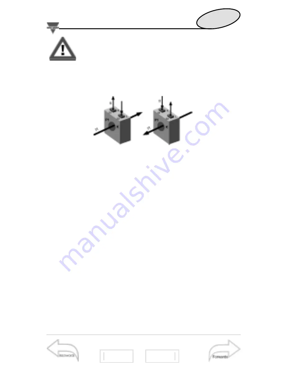
The variables measured by the instrument are
correct if the polarities of the inputs have been
observed (as shown in the figure below); if not,
measuring and retransmission errors may occur due to
the wrong direction of the current flowing in the primary
/ secondary of the connected current transformer.
Example 2 “Use of digital filter”:
it’s necessary to stabilize
the displayed value of the VL1-N variable that varies between
222V and 228V. The parameters of the digital filter are to be
set as follows:
•
rnG: the variable varies within the average value, the
amplitude of which is equal to ±1.3% of the variable’s rated
value, calculated as follows:
(228-222)/2=±3V, then ±3*100/231V=±1.3%, where 231V
is the phase-neutral rated value of a 400V input range. The
“range” parameter, that corresponds to the action range of
the digital filter, is set at a value which is slightly higher than
the percentage amplitude of the fluctuation: e.g. 2%.
•
CoE: if the new value acquired by the instrument is with-
in the filter’s action range, then the new displayed value is cal-
culated by summing algebraically to the previous value the
variation divided by the filtering coefficient. As a conse-
quence, a value which is higher than this coefficient implies a
longer settling time and therefore improves the stability. The
latter can also be improved by increasing the filtering coeffi-
cient: the admitted values are within 1 and 16. Enter the value
in consecutive attempts until you reach the desired stability.


