Manuale Utente / User Manual
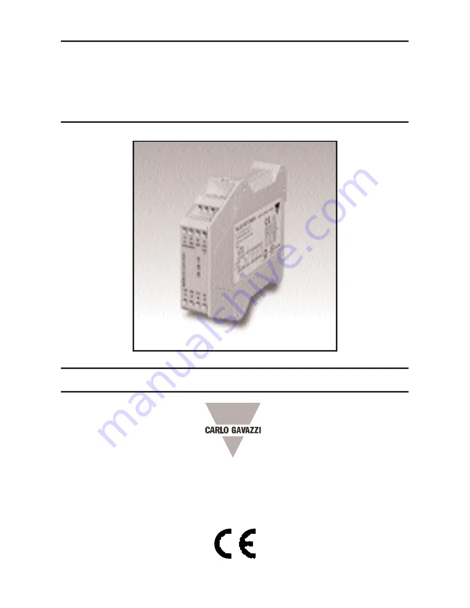
MODULI DI SICUREZZA
SAFETY
MODULE
NLG13D..
Страница 1: ...Manuale Utente User Manual Manuale Utente User Manual MODULI DI SICUREZZA MODULI DI SICUREZZA SAFETY SAFETY MODULE MODULE NLG13D NLG13D...
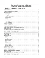
Страница 2: ...17 DATI TECNICI TECHNICAL DATA 20 INDICE T INDICE TABLE OF CONTENTS ABLE OF CONTENTS 2 INTRODUCTION 10 FUNCTION 10 INSTALLATION 10 Warning 10 Wiring 11 Terminals coding 11 Power supply 11 Input 11 ST...
Страница 3: ...delle cen traline si intendono Azionati o attivati nel caso in cui l ESPE presenti raggi non interrotti riarmo attivato sia ali mentato e non vi siano guasti nel sistema In questa condizione le uscit...
Страница 4: ...o ed al polo negativo della sorgente di alimentazione DC Il negativo di alimentazione dell ESPE DEVE coincidere con il negativo della ali mentazione del modulo vedi figu re con esempi INGRESSI Il modu...
Страница 5: ...azioni in cat 2 preve dere un test interrompendo i raggi dell ESPE con la periodicit indivi duata nelle relative norme Il modulo abilitato a chiudere le uscite sicure solo se entrambi i ter minali S11...
Страница 6: ...e del pulsante di START trascorra un tempo di almeno 500 ms Uguale intervallo deve tra scorrere tra l apertura del pulsan te di START e la sua richiusura nel caso di chiusura degli ingressi a START gi...
Страница 7: ...e aperte e aperta con uscite sicure chiuse PRECAUZIONI DI UTILIZZO L ESPE deve essere installato in posizione tale da assicurare che l operatore non possa raggiun gere la zona pericolosa quando esisto...
Страница 8: ...collegati Il modulo non prevede manuten zione interna E necessario perio dicamente ed a macchina e modu lo disalimentati pulire il modulo di sicurezza ed i relativi dispositivi di comando e di attuaz...
Страница 9: ...etto comportamento del sistema deve essere verifica to da un dispositivo di pi alto livello ad esempio dalla macchi na in cui la coppia modulo barrie ra installata oppure da un dispositivo di controll...
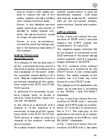
Страница 10: ...achinery Directives NOTE The input terminals of the module are intended to be operated when the light beams are not interrupted the ESPE and the module are correctly supplied and there are not fault c...
Страница 11: ...als respectively to the positive and negative poles of the DC power supply source The negative sup ply terminal of the ESPE must be connected to the same negative pole of the DC power supply sour ce t...
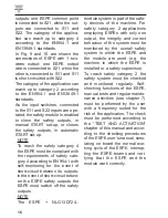
Страница 12: ...PE with one relay two wires output connect the output wires to the S11 and S22 terminals short circuit S11 with S22 lea ving S12 not connected fig 10 max Safety cat 2 For safety cat 2 applications a p...
Страница 13: ...500 ms from the operated status of the input contacts to the pushing of the START button The same delay is necessary between the START button releasing and re operating if the input terminals have be...
Страница 14: ...s verify that the auxiliary output is closed when the safety outputs are open and that the auxiliary output is open when the safety outputs are clo sed USAGE PRECAUTIONS The ESPE must be carefully ins...
Страница 15: ...verify the integrity of the module external device system The safety module doesn t require internal maintenance it must be periodically cleaned with plant and module powered off together with all th...
Страница 16: ...short circuit between its outputs in the event of short circuit betwe en the ESPE safety outputs the ESPE must switch off the safety outputs NOTE The ESPE NLG13D724 module system is part of the safe t...
Страница 17: ...FIGURE E TABELLE FIGURES AND TABLES 17 Fig 1 Schema circuitale dei moduli NLG13D724 NLG13D724 circuit diagram Fig 2 Diagramma funzionale Functional diagram mod SC e and DC...
Страница 18: ...uscite PNP a 1 filo Two 1 wire PNP outputs Fig 4 ESPE 2 uscite a rel a 1 filo Two 1 wire relay outputs Fig 5 ESPE 1 uscita PNP a 1 filo One 1 wire PNP output Fig 6 ESPE 1 uscita a rel a 1 filo One 1 w...
Страница 19: ...cita a rel a 2 fili One 2 wires relay output Fig 9 ESPE 1 uscita PNP a 2 fili One 2 wires PNP output Fig 7 ESPE 2 uscite PNP a 2 fili Two 2 wires PNP outputs Fig 8 ESPE 2 uscite a rel a 2 fili Two 2 w...
Страница 20: ...supply 24 Vdc 15 10 Assorbimento Current drain 70 mA 24Vdc a vuoto no load Potenza assorbita Power Drain max 5 VA Categoria sic Safety Category 4 EN954 1 and EN13849 1 Performance Level e EN13849 1 P...
Страница 21: ...ts closed max 150 ms Contemporaneit alla chiusura tra gli ingressi input channel simul taneity during outputs closing infinita infinite Ritardo tra azionamento ingressi e attivazione START input opera...
Страница 22: ...ili ai morsetti Cross Section and type of the cables to connect to the termi nals 0 05 3 mm2 AWG 30 12 Rigido e flessibile in rame 60 C o 75 C stranded or solid wire 60 or 75 C copper conductor Coppia...
Страница 23: ...according to the norm EN ISO 13849 1 2008 The EMC Directive 2004 108 EC EN 61000 6 3 Generic Emission Standard Residential commercial and light industry EN 61000 6 2 Generic Immunity Standard Industr...
Страница 24: ...CARLO GAVAZZI si riserva il diritto di apportare modifiche senza preavviso CARLO GAVAZZI reserves the right to make changes without prior notice 8021008 Mod NLG13DB24...