


NOTE
WA R N I N G
!
The 9060 Control
Unit must be located a minimum of 5’ (1.5 m) outside of
what is considered to be the hazardous area. Any mounting
method used must properly support the unit to a minimum
of 4X the unit weight.
See manual CP-13-07 for the installation
instructions for the 9060 control unit.
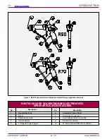
For safe use these applicators 79500, 79501
and 79523 must be used with the appropriate 9060
Control Unit part number 80131-XXX. For exact
configurations see the approved configuration draw-
ings in the front of this manual.
CAUTION
!
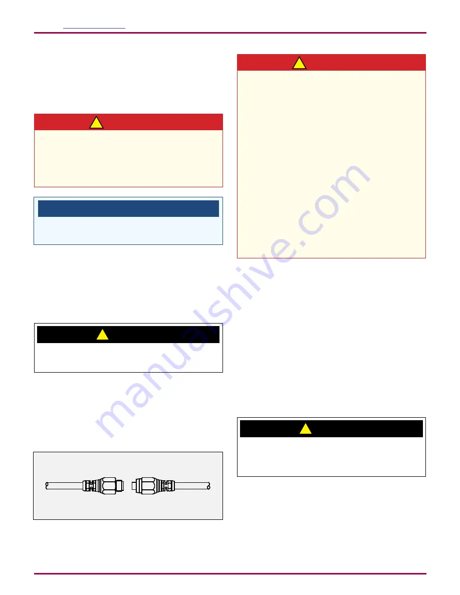
LOW VOLTAGE CABLE
Connect the low voltage cable from the control unit to the
applicator using a wrench to tighten.
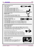
Figure 10: Daisy Chained Cable
DO NOT
over-tighten the low voltage connection
at the applicator. The plastic parts could be damaged.
With the Vector design, multiple cables may be connected
together to create the length required, up to a maximum of
30m (100 ft.). To connect the cables, insert the male end
of one cable into the female end of the other. Tighten both
cable connectors against each other using two (2) 16mm
(5/8") open-end wrenches.
WA R N I N G
!
The electrical discharge that is available from
the charging electrode must not exceed 0.24 mJ of
energy. To achieve this limit, any flow of energy from
the paint supply through the paint line to the appli-
cator electrode must be prevented by grounding the
paint line at the applicator handle.
Verify that the applicator handle is actually ground-
ed before operating it! This is done with a fully
connected and operational system, by placing
one lead of an ohmmeter to the handle and the
other to the building electrical ground (cold water
pipe, building structure, steel, etc.). This reading
should be essentially zero.
If a greater reading is obtained, check that the
control unit is grounded. (See the control unit
manual for "Grounding Procedure.")
CAUTION
!
FILTERS
1. Install an air filter assembly on the air inlet of the control
unit. The filter should be 5 micron with a maximum
working pressure of at least 100 psig (6.9 bar). Screw
the fitting into the filter inlet. The filter MUST be installed
with the arrow pointing in the direction of flow. (Refer to
the appropriate Filter Assembly manual for "Installation
Instructions".)
When the applicator is triggered, the resulting air flow
closes the contacts of the air flow switch, thereby acti-
vating high voltage at the applicator.
2. Ransburg recommends that a fluid filter be installed
at the output of the fluid supply (pressure pot,
pump, circulating system, etc.). It is the end user's
responsibility to install the proper filter that meets their
system's requirements.
An air filter
MUST
be installed to permit proper
functioning of the air flow switch inside the control unit.
This unit must filter particles 5 microns and larger.
AH-06-01-R17 (08/2019)
26 / 79
www.carlisleft.com
INSTALLATION
EN


