background image

TROUBLESHOOTING SPRAY PERFORMANCE

Always engage trigger lock and relieve fluid pressure.

!


CAUTION

PROBLEM

CAUSE

CORRECTION

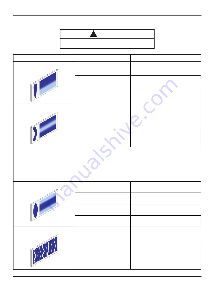
Heavy top or bottom pattern.

Material build-up on air cap, plugged 

horn holes, center holes or jets.

Soak cap or tip in suitable solvent and thoroughly 

clean.

Material build-up on fluid tip exterior or 

partially plugged fluid tip.

Replace fluid tip or air cap if necessary.

Fluid tip or cap dirty or damaged.

Replace fluid tip or air cap if necessary.

Heavy right or left side pattern.

Left or right side horn holes plugged.

Soak cap or tip in suitable solvent and thoroughly 

clean.

Dirt or damage on left or right side of 

fluid tip exterior.

Replace fluid tip or air cap if necessary.

Remedies for the top-heavy, bottom-heavy, right-heavy and left-heavy patterns.

Determine if the obstruction is on the air cap or the fluid tip. Do this by making a test spray pattern. Then, rotate the air cap and tip one-half 

turn and spray another pattern. If the defect is inverted, obstruction is on the air cap. Clean the air cap as previously instructed. Also check for 

dried paint just inside the cap center hole opening, remove by washing with solvent.

If the defect is not inverted, it is on the fluid tip. Clean tip. If problem persists, renew tip.

Heavy center pattern.

Pattern adjustment valve set too low.

Turn out counter clockwise to achieve correct 

pattern.

Too much material.

Reduce fluid pressure.

Material too thick.

Thin to correct consistency.

Atomizing air pressure too low.

Increase air pressure.

Intermittent or 'fluttering' spray fan.

Fluid tip not seated correctly in gun 

head.

Remove fluid tip, clean components, check 

cone seating on tip and gun for damage or 

contamination.

Partially obstructed fluid passage or 

hose.

Clean or replace.

EN

77-3130-R4  (5/2019)

6 / 16

www.carlisleft.com

Содержание Binks TROPHY AA 1600

Страница 1: ...cap will also add a secondary atomization based on its configuration This is done by utilizing a separate air supply to the gun You may also control the pattern size using the spreader valve This dual...

Страница 2: ...installation stated within the product manuals have been complied with and also installed in accordance with any applicable local codes of practice The object of the declaration described above is in...

Страница 3: ...E RELIEF PROCEDURE Always follow the pressure relief procedure in the equipment instruction manual NOISE HAZARD You may be injured by loud noise Hearing protection may be required when using this equi...

Страница 4: ...the required material coverage and spraying speed are achieved you may need to switch to a different fluid tip FLUID TIP SELECTION Factors to consider in selecting a fluid tip for an air assist airle...

Страница 5: ...try to clear tip of any debris If that fails turn off fluid supply Engage trigger safety Remove air cap nozzle guard assembly and spray tip Clean or replace the twist tip item 10 Needle is damaged or...

Страница 6: ...he obstruction is on the air cap or the fluid tip Do this by making a test spray pattern Then rotate the air cap and tip one half turn and spray another pattern If the defect is inverted obstruction i...

Страница 7: ...n too far from surface Check distance Runs and sags Too much fluid flow Adjust gun or reduce fluid pressure Material too thin Mix properly or apply light coats reduce fluid flow Gun tilted at an angle...

Страница 8: ...600 SPRAY GUN ASSEMBLIES 1 2 3 4 5 6 7 8 9 12 11 10 13 16 14 15 17 17e 18 19 17f 17b 3a 3b 3c 3d 9a 17d 17c 17g 17a 4a 4b 4c 4d 4e 20 SOLD SEPARATELY SOLD SEPARATELY EN 77 3130 R4 5 2019 8 16 www carl...

Страница 9: ...0 REVERSABILE TWIST TIP 11 54 5924 K HVLP TWIST TIP AIR CAP ASSEMBLY 1 12 SEE PAGE 10 FLAT TIP ASSEMBLY SEE PAGE 10 FINE FINISH FLAT TIP ASSEMBLY 13 54 6030 K AA10 AIR CAP ASSEMBLY 1 14 SN 9 K3 AIR IN...

Страница 10: ...NING RING 1 1 6 TWIST TIP GUARD 1 1 TEST AIR CAP KITS 54 5932 K HVLP LVMP 54 6030 K 54 5890 K 54 5878 K 54 5795 K 54 5797 K ITEM NO PART NO DESCRIPTION AA10 AA10 9X H 9X H 9X L 1 SEAL REMOVAL TOOL 2 s...

Страница 11: ...ass valve if so equipped 3 Place the material suction tube into a solvent container If the pump is directly immersed in material remove the pump and immerse it in a container containing solvent 4 Enga...

Страница 12: ...MAINTENANCE DISASSEMBLY 14mm 4 3b 2 3a 1 16mm 5 6mm 20 3c 20 3d 12 13 9 8 19mm 14 15 14mm 17 16mm 8mm 3c 7 6 16 77 3130 R1 0 Page MAINTENANCE Disassembly EN 77 3130 R4 5 2019 12 16 www carlisleft com...

Страница 13: ...13 15 ft lbs 12 13 80 98 Nm 18 22 ft lbs 14 15 14mm MAINTENAN Assembly 3d 20 5 1 20 3a 3b 2 16mm 14mm 4 17 16mm MAINTENANCE Assembly 17 20 Nm 13 15 ft lbs 3d 20 3c 20 5 6mm 6 7 Nm 5 6 ft lbs 1 20 3a 3...

Страница 14: ...300mm 12in RS 1714 350mm 14in RS 1716 400mm 16in RS 1718 450mm 18in RS 1816 46mm 018in 400mm 16in 681 CC 180 GPM STANDARD TIP SIZES OFFERED PART NUMBER ORIFICE FAN WIDTH CAPACITY RS 1906 48mm 019in 15...

Страница 15: ...38mm 015in 908 CC 240 GPM 9 317 75 43mm 017in 1173 CC 310 GPM 9 319 75 48mm 019in 1457 CC 385 GPM 9 409 75 23mm 009in 200mm 8in 341 CC 090 GPM 9 411 75 28mm 011in 454 CC 120 GPM 9 413 75 33mm 013in 68...

Страница 16: ...tions Region Industrial Automotive Automotive Refinishing Americas Tel 1 800 992 4657 Tel 1 800 445 3988 Fax 1 888 246 5732 Fax 1 800 445 6643 Europe Africa Middle East India Tel 44 0 1202 571 111 Fax...

Отзывы: