background image

7. Troubleshooting Guide

Heater Power Problems

Problem 

Heater lamps come on immediately when disconnect is closed.

Possible Cause and Corrective Action 

With  power  OFF,  measure  the  resistance  from  the  lamp  wires  to  ground.  The

measurement  should be more than 100 K ohms. If it is less than 100 K, check the lamp wiring

and heater head for shorts to ground. Check for a bad firing circuit board or a shorted SCR

by: exchanging the firing circuit board with one from a known good control. Does the problem

follow the firing circuit board or does it stay with the SCR – replace the defective component.

Contactor held closed – failed ON. Replace the contactor.

Problem 

Heater lamps do not come on.

Possible Cause and Corrective


Action 

Is the Power On/Off button illuminated, is the temperature controller on? - Check that

incoming line power is present; transformer fuses, primary and secondary are good.

Do the contactors energize when the Cycle Start button is pressed? – Check for loose wires

associated with the contactors,change the temperature controller.

Check that the set point (bottom display) is higher than the process temperature (top

display).

Are the line fuses in front of the contactors good – check voltage on the load side of the

fuses or remove the fuses and check with an ohmmeter.

Is the green LED on the firing circuit lit? – Check that the firing circuit has 24 vac, with an

ammeter check that the 4-20ma input signal is present from the temperature

controller. If the 4-20ma signal is not present, see the section “No Output Signal

from Temperature Controller”.

Do any of the zones function? – If the above points have been checked, confirm that

there is a complete circuit through the lamps and all wiring is tight – change the

SCR.

Are all zones dead? – Zone A should function regardless of the zone switch setting, there is

only one firing circuit for all zones - change the firing circuit

Содержание BGK AutoCure 6000-2216

Страница 1: ...AutoCure 6000 2216 Overhead Heater Assembly and Operating Manual ...

Страница 2: ...amp Instruction Replacement Procedure 10 5 HEATER POSITION INSTRUCTIONS General Instructions Read All 11 Heat Masking 12 Positioning Set up of Heater Head Instructions 12 13 Yellow Pendent for overhead arm movement 14 6 MAINTENANCE Actuator Pivot Points 15 Lamps Reflectors and Heat Sensor Pyrometer Lens 15 7 TROUBLESHOOTING GUIDE Heater Power Problems 16 Temperature Controller Problems 17 Temperat...

Страница 3: ...34 Calibration Adjustment 35 Lock Out the Comm Box 36 11 SINGLE HEAD BACK PANEL BILL OF MATERIAL 37 38 12 JUNCTION BOX 39 13 MECHANICAL DRAWINGS PARTS LIST 3 pgs 40 42 14 TABLES 4 pgs 43 46 15 AUTOCURE MODEL NUMBERS 47 AC6 2216 480 SP 47 Electrical Schematic 2 pgs 48 49 Spray Bake 50 Heater Heads 5 pgs 51 55 Recommended Spare Parts 56 16 BGK CARLISLE FLUID TECHNOLOGIES CUSTOM PRODUCTS WARRANTY 57 ...

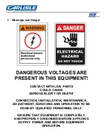
Страница 4: ... WITH LIVE PARTS COULD CAUSE SERIOUS INJURY OR DEATH CONNECTION INSTALLATION MAINTENANCE ADJUSTMENT SERVICING AND OPERATION TO BE DONE BY QUALIFIED PERSONNEL ONLY ENSURE THAT EQUIPMENT IS COMPLETELY AND PROPERLY GROUNDED BEFORE APPLYING SUPPLY POWER AND BEFORE EQUIPMENT OPERATION ...

Страница 5: ... objects to be sprayed and all other electrically conductive objects in the dispensing area Improper grounding or sparks can cause a hazardous condition and result in fire explosion or electric shock and other serious injury PROP 65 WARNING WARNING This product contains chemicals known to the State of California to cause cancer and birth defects or other reproductive harm WEAR RESPIRATOR Toxic fum...

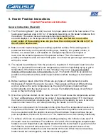
Страница 6: ...intensity without warning to unaware personnel 7 Heater surfaces can become hot when used at high power for extended periods Use caution whenever handling heater head s The heater head s have black insulated handles to use for moving or manipulating heater head s 8 Do not move heater when in operation because it will move the temperature sensor viewing area and the heater head s distance to produc...

Страница 7: ...T HANDLE INFRARED LAMPS WITH BARE HANDS Remove any contamination with alcohol and a clean soft cloth Contamination on quartz tubes allows the quartz to overheat which leads to premature lamp failure PYROMETER POSITIONING BEAM A class 2 laser emits in the visible region 635 870mN at 1mW of power The blink reflex of the human eye aversion response will prevent eye damage unless the person deliberate...

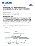
Страница 8: ...ay indicates the mode of the heating cycle and the process temperature During the Ramp mode the upper display will toggle between the process temperature and ramping Once the cure temperature set point has been reached the upper display will toggle between the hold time remaining in minutes and the process temperature When the hold time becomes less than one minute the upper display will toggle be...

Страница 9: ...ress the to exit setup menu 6 Set auxiliary heater off or on 7 Press the cycle start Double Ramp 1 Turn power on 2 Turn positioning beam on and position heater 3 Set controller parameters 4 Hold the button for 1 2 seconds a Set rp1 ramp time in minutes Press b Set ct1 cure temp in degrees Press c Set hd1 hold time in minutes Press d Set rp2 2nd ramp time in minutes Press e Set ct2 2nd cure temp in...

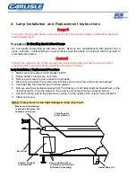
Страница 10: ...ain system circuit breaker is OFF 2 Rotate heater so lamps are horizontal 3 Remove end covers to gain access to lamp leads 4 Disconnect wire from the ceramic terminal block and remove lamp that is being replaced 5 Carefully slide the lamp through the lamp support 6 Remove electrical insulation sleeves from the old lamp on both lamp leads and install them on the new lamp leads Push the sleeve to th...

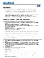
Страница 11: ...e heated area 4 Before heating a repair determine if there are any types of reinforcements or extra thicknesses of metal in the area to be cured These areas will heat at different rates and not achieve the same temperature as the single thickness metals without reinforcements Aim the heat sensor on or near the multiple thickness or reinforced areas so they will be fully cured 5 Once the cycle has ...

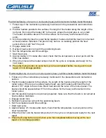
Страница 12: ...ure and time settings 7 Start heat cycle 8 Approximately 3 5 minutes after start check that the temperature is at set point and the timer has started 9 When the timer and the heater lamps shut off the cycle is complete and ready for the next repair 10 Press the E stop button on unit when cycle has completed before moving unit to next repair or in to storage position Positioning Set Up of a heater ...

Страница 13: ...ton on unit when cycle has completed before moving unit to next repair or in to storage position Positioning Set Up of an arm on rocker panels heavy reinforcements multiple metal thickness 1 Follow any of the instructions previously mentioned in the precautions and instructions section 2 Position heaters parallel to the surface the length of the heater along the length of the rocker panel If there...

Страница 14: ...e current heating cycle NOTE These are procedures that give reliable results for most repairs Unusual or complex repairs might need modified procedures Contact BGK service for assistance Yellow Pendent for overhead arm movement The yellow pendant has a button labeled Beam On and Start Toggling the Beam on activates the position beam and toggling the start button will initiate the heating cycle Ref...

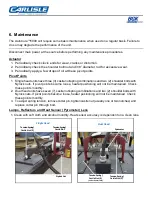
Страница 15: ...s with Nylock nuts If pivot points become loose heater positioning will not be maintained Check these points monthly 2 Dual head units have seven 7 castle nut spring combinations and two 2 shoulder bolts with Nylock nuts If pivot points become loose heater positioning will not be maintained Check these points monthly 3 To adjust spring tension remove cotter pin tighten castle nut usually one or tw...

Страница 16: ... transformer fuses primary and secondary are good Do the contactors energize when the Cycle Start button is pressed Check for loose wires associated with the contactors change the temperature controller Check that the set point bottom display is higher than the process temperature top display Are the line fuses in front of the contactors good check voltage on the load side of the fuses or remove t...

Страница 17: ...roller at pins 9 10 If the 0 5v signal is not present confirm that the Raytek pyrometer is functioning Is the LCD display lit If not check that the Raytek input power 12 vdc is present check that the power supply board is supplying 12 vdc TB 4 replace the temperature controller Raytek or the power supply board Problem Temperature controller output signal is present but heater lamps do not come on ...

Страница 18: ...eone watch for sudden temperature changes If this happens replace the cable Problem The temperature display jumps up or down many degrees within a second Possible Cause and Corrective Action Read the instructions in the manual on how to position and run the heater Clean the temperature sensor lens as described in maintenance section The optical pyrometer is not seeing the surface of the object bei...

Страница 19: ...esume Feature Disabled Unexpected or invalid interrupt Check sensor wiring and input Check Sensor polarity Correct problem and Reset controller Press Any Key to perform a soft reset and reinitialize controller No further resume actions available Reset Controller Ramp Soak Errors 02 Recipe Empty i e no non zero ramp times 05 Insufficient Setpoint Process Value Deviation 8 TEMPERATURE CONTROLLER ERR...

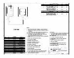
Страница 20: ...RE NUTS STRAIGHT THROUGH STRAIN AC 200026 RELIEF I 2 LOOSEN NUT AND REMOVE NUT GROMMET AND 3 WASHERS DISCARD ONE WASHER NOTES CONTD 6 WRAP 3 3 COPPER TAPE AROUND PYROMETER TO ENSURE RUNNING m USE AC 200198 WRAP 4 5 OF TAPE AROUND LASER AC 65427 21 APPLY SHRINK TUBING ONTO MESH AFTER TRIMMING WIRES TO 7 APPLY THERMAL JOINT COMPOUND USING APPUCATOR AND SPREAD ACROSS ENTIRE CIRCUMFERENCE USE AC 20019...

Страница 21: ... 61228 INSULATOR PYROMETER 11 AC 61227 MOUNT INSULATOR PYROMETER 12 AC 61232 HOUSING PYROMETER 13 AC 61230 COVER PYROMETER 14 AC 200099 3 SCREW MACH FL HD SLOT 8 32 X 2 750 15 AC 200032 STANDOFF HEX 8 32 X 750 16 AC 13938 WASHER LOCK EXTERNAL TOOTH 8 SST 17 AC 10142 8 32 SST TRUSS HEAD 18 AC 200088 CAUTION LABEL 4 3 2 18 FINISH 2 NOTE 6 7 NEXT ASSY PART NO DRAWING NO AC 61231 D 11 C 14 B REV SHEET...

Страница 22: ......

Страница 23: ......

Страница 24: ...peratures to achieve the proper cure of the paint Equipment Required Hand held Infrared pyrometer in good working order with a current calibration label Pyrometer with laser aiming is preferred A good condition scrap painted door fender or test panel on which to perform the calibration is required White or light color is preferred A 1 Phillips screwdriver RAYMID10LT Pyrometer Sensor manufactured b...

Страница 25: ... the sensor with wire nuts The wire gauge will be changing from 20 AWG to 22 AWG effective upon change over in February 2015 Sensor Connections Brown white green and yellow remain the same colors between old and new units OLD UNIT RAYMID10LT Power Connections Black Wire GND next to 8 32V Red Wire 8 32V White Wire OUT2 Blue Wire GND next to TC NEW UNIT RAYMI3D10LTS ...

Страница 26: ...ated for hazardous environment nor are they ATEX approved They are CE rated only The new unit is hinged as shown in Figure 1 3 Performance the new sensor is equal a direct replacement to the older unit There is no change in emissivity or response time between units they are equal Figure 1 3 Figure 1 4 ...

Страница 27: ... pyrometer side and remove wires from housing 4 Open enclosure on top of heat sink and isolate wires for laser black red leads 5 Clip leads leaving enough wire to strip and re connect with crimp connections 6 Loosen and remove standoffs 7 Remove insulating plate 8 Remove heat sink then remove pyrometer Replacement of New Pyrometer Sensor ...

Страница 28: ...g using schematic in Step 1 17 Reconnect wires in wire harness as shown above 1 Open Housing and loosen 4 terminals to remove pyrometer Loosen 4 terminals to remove connection to AutoCure Arm as shown below 2 Open New Housing and loosen 4 terminals as shown above to remove pyrometer 3 Disconnect wires in wire nuts 4 On New Housing Loosen and remove nut grommet and three washers on thermocouple sid...

Страница 29: ...ert and tighten down to 20 Nm 9 From AC arm insert nut AC 200104 Nylon washers and Grommet similar to diagram in step 5 10 Insert leads into terminals indicated in step 1 Reconnect leads into wire terminals 11 Tighten down nut to 20 Nm 12 Verify calibration per SI B 11 02 1 see next page ...

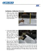
Страница 30: ...multiple thickness metals within about 12 inches of the mark 3 Then on the arm control panel push the Positioning Beam On button Locate the positioning beam red dot on the test surface on the X or dot you made above Make sure you maintain the 10 inch gap between the test surface and the heater head This dot is also the point where the hand held pyrometer will be aimed during calibration to read th...

Страница 31: ...handheld pyrometer measure the temperature of the target about 1 to the right of the positioning beam spot Figure D Hold the hand held pyrometer as close to 90 to the testing surface as possible by the edge of the heater head This is critical for an accurate and consistent reading 3 Compare the handheld reading with the process temperature upper display on the temperature controller If they are wi...

Страница 32: ...e setting should be highlighted Press the arrows keys until the correct settings is display 0 5V After settings is correct press the enter button to save setting OUT2 Value Using the arrow keys until OUT2 Value is displayed Verify the setting for mode is Tobject If the setting is incorrect press the enter button and the setting should be highlighted Press the arrows keys until the correct settings...

Страница 33: ...ld be highlighted Press the arrows keys until the correct setting is displayed F or C After settings is correct press the enter button to save setting 2 Position the testing surface door fender etc in front of the heater head Adjust the heater head about 10 away from the painted test surface Approx an open hand width ...

Страница 34: ...ea 2 Press the Cycle Start button two times with in two seconds Lamp cycle should begin with a ramp up to the final cure ramp settings They will be rp1 set points on a single ramp setup and rp2 on a dual ramp setup See figure A The temperature set point will be displayed on the bottom display of the temperature controller The upper display will alternate between rp_ and the actual temperature feed...

Страница 35: ...re number using the down button After adjusting the value press the enter button to save the value 3 If the reading on the handheld pyrometer is less than the process temperature on the temperature controller increase the temperature number using the up button After adjusting the value press the enter button to save the value 4 When you are within 5 degrees difference between the handheld pyromete...

Страница 36: ...er Lock is displayed Verify the setting YES If the setting is incorrect press the enter button setting should be highlighted Press the arrows keys and the until the correct settings Yes is displayed After settings is correct press the enter button to save setting 3 Verify the padlock is displayed as shown Procedure is completed ...

Страница 37: ......

Страница 38: ......

Страница 39: ...D 8X6X6 AC6 AC 200188 DEBURR SHARP EDGES SIZE JOB NO QTY AS SHOWN 1 QTY OPPOSITE 2 PROJ MGR REL DATE NEXT ASSY CTL Parts List DESCRIPTION PART NUMBER TYPE QTY ITEM 6 CUT DIN RAIL P 1 1 J BOX 8X6X6 A8066CH P 1 2 INNER PANEL 8X6 A8P6 P 1 3 AB IEC ONE CIRCUIT FEED THROUGHT BLOCK AC 200058 P 3 4 AB END ANCHOR AC 200059 P 2 5 AB END BARRIER AC 200060 P 1 6 AB IEC ONE CURCUIT FEED THROUGH GND BLOCK AC 2...

Страница 40: ...D 1 USE ACI DRAWING FOR ASBY OF AC 182 8 2 APPLY THREAD LOCK BLUE 7NMl3 A MODIFICA TIONSANDI FDATES B OONlROLSNOWONUNfT SEEIAM FI E C at oHGEDACT JATORBRKTFORMORETRA REPUICED N NXlEDlllHB IACOvER F REPI ACEDACTW TOR RE IISEDMTGPARTS DETAIL C 3 NOT SHOWN0 0B usEAC 3832NYl l 11r crt m rnlJ7 rcu 1A NEXTAlJB f PNUNO DRAWINGNO ...

Страница 41: ...A DETAIL J SCALE0 40 1 REMOVET1 11SBOLTAFTERINSTAI I ATION ...

Страница 42: ...N INNER SIDEONTHE PANB WHEN INSTALLINGA IK ALI OWINGTI E ELECTRIOO P IEL TO SIT UPOFF THE SURf ACEOF Tl INNER PANELOF ITEM 47 AVK LOCATIONS AC6 3MOREOl ITEM21ARE LOCf ffOONCf P 810EOI u DETAIL G SCALE 1 2 ARM MAIN NEXTAlJB f PNUNO DRAWINGNO ...

Страница 43: ......

Страница 44: ......

Страница 45: ......

Страница 46: ......

Страница 47: ...AUTOCURE MODEL NUMBER AC6 2216 480 SP ...

Страница 48: ......

Страница 49: ......

Страница 50: ...e Four configurations 240V 1ø 480V 1ø 240V 3ø 480V 3ø 2 Modes of Operation Local There is a 2 position switch on the front of the box to switch from Spray to Bake The 2 terminals for the remote mode must be jumped Remote There are 2 terminals to connect a remote dry contact from another control The switch must be in the bake position if the remote contacts are used ...

Страница 51: ... 3 POLE CERAMIC 600V 28 8 AC 50686 3 SCREW CAP SOCKET HD 8 32 X 1 00 30 24 AC 47799 8 32 SST MACH NUT 31 4 39331 LAMP IR 1600W 240V CER CL 19 7OAL 16 0L 32 25 AC 3887 10 EXTERNAL LOCK WASHER 33 2 AC 50686 1 PYROMETER SCREWS 34 1 AC 42936 PYROMETER 35 25 AC 4002 10 32 AVK 1ST GRIP 36 50 AC 200098 1 AVK 1ST GRIP 8 37 8 AC 200097 RIVET BLACK ALUMINUM 43 38 50 AC 13938 WASHER LOCK EXTERNAL TOOTH 8 SST...

Страница 52: ...ED OR IT S CONTENTS DISCLOSED WITHOUT AUTHORIZATION z 2002 BGK FINISHING SYSTEMS ASSY HEATER 2216 SHOP NEXT ASSY ENG REL PART NO SCALE CTL 6 13 2012 JOB NO MATERIAL FINISH DATE DRAWN 2OF DUE REV C PROD REL ACH6 2216 36 50 31 4 4 2 11 4 27 6 28 8 25 4 30 24 37 8 38 50 7 50 7 50 38 50 36 50 36 50 38 50 7 50 11 4 10 2 TYPICAL TYPICAL TYPICAL 3 2 12 4 43 44 46 PRESS NUT INTO PLACE W PRESS TOOL ON WORK...

Страница 53: ... OR IT S CONTENTS DISCLOSED WITHOUT AUTHORIZATION z 2002 BGK FINISHING SYSTEMS COVER END 2 LAMP 3 CENTER SHOP NEXT ASSY ENG REL PART NO SCALE CTL 6 13 2012 JOB NO MATERIAL FINISH DATE DRAWN 3OF DUE REV C PROD REL ACH6 2216 NUMBER PART No DESCRIPTION 1 AC 200098 1 AVK 8 32 2 AC 4002 AVK 10 32 3 AC 200097 BLACK RIVET 4 AC 4012 AVK 3 8 4 3 2 1 2 1 1 1 1 1 TYPICAL TYPICAL TYPICAL TYPICAL TYPICAL TYPIC...

Страница 54: ...12 FINISH MATERIAL CTL DATE 1 32 030 TOLERANCES REL BY DRAWN JOB NO SCALE JOB NO ENG REL 2 PLACE 3 PLACE SHOP QTY ACH6 2216 PARALLEL SERIES AC 200048 13 AC 200048 13 AC 200192 GROUND WIRE AC 200048 25 AC 200048 13 AC 200048 13 AC 200192 GROUNDWIRE B B B B B REMOVE ALL UNUSED HARDWARE FROM CIRCUITS INSIDE CERAMIC BLOCK REMOVE ALL UNUSED HARDWARE FROM CIRCUITS INSIDE CERAMIC BLOCK REMOVE ALL UNUSED ...

Страница 55: ... 5 SHEET THIS MATERIAL IS THE PROPERTY OF BGK FINISHING SYSTEMS IT MUST NOT BE COPIED OR IT S CONTENTS DISCLOSED WITHOUT AUTHORIZATION z 2002 BGK FINISHING SYSTEMS SHOP NEXT ASSY ENG REL PART NO SCALE CTL 6 13 2012 JOB NO MATERIAL FINISH DATE DRAWN 5OF DUE REV C PROD REL ACH6 2216 38 7 27 36 41 42 X2 ASSY REFERENCE SHEET ONE ...

Страница 56: ...3 FC 1 003317 Firing Circuit Board PWR CTRLR 4 20MA 240V 380V 480V SCR 103 SCR 104 1 002985 POWER CONTROLLER SCR 40A 240V 380V 480V 103 2 AC 200051 POWER CONTROLLER THERMSTRATE H CR110A CR110B CR116 1 062486 RELAY 1 PDT 24VDC AC 1 AC 200064 LASER KIT Targeting laser only PYR 118 1 AC 61231 PYROMETER ASSEMBLY KIT Complete Bridge 110 1 062001 RECTIFIER BRIDGE 25A 50V 1 AC 73709 ACTUATOR SS114 1 0645...

Страница 57: ...al assistance or to locate an authorized distributor contact one of our international sales and customer support locations For the latest information about our products visit www carlisleft com Region Industrial Automotive Automotive Refinishing Americas Europe Africa Middle East India China Japan Australia Carlisle Fluid Technologies is a global leader in innovative finishing technologies Carlisl...

Отзывы: