background image

Model 301GAS burner — Instruction manual

Carlin part number MN301GAS Rev. 11/24/14

– 17 –

Where appliance instructions differ from this manual, follow the appliance instructions.

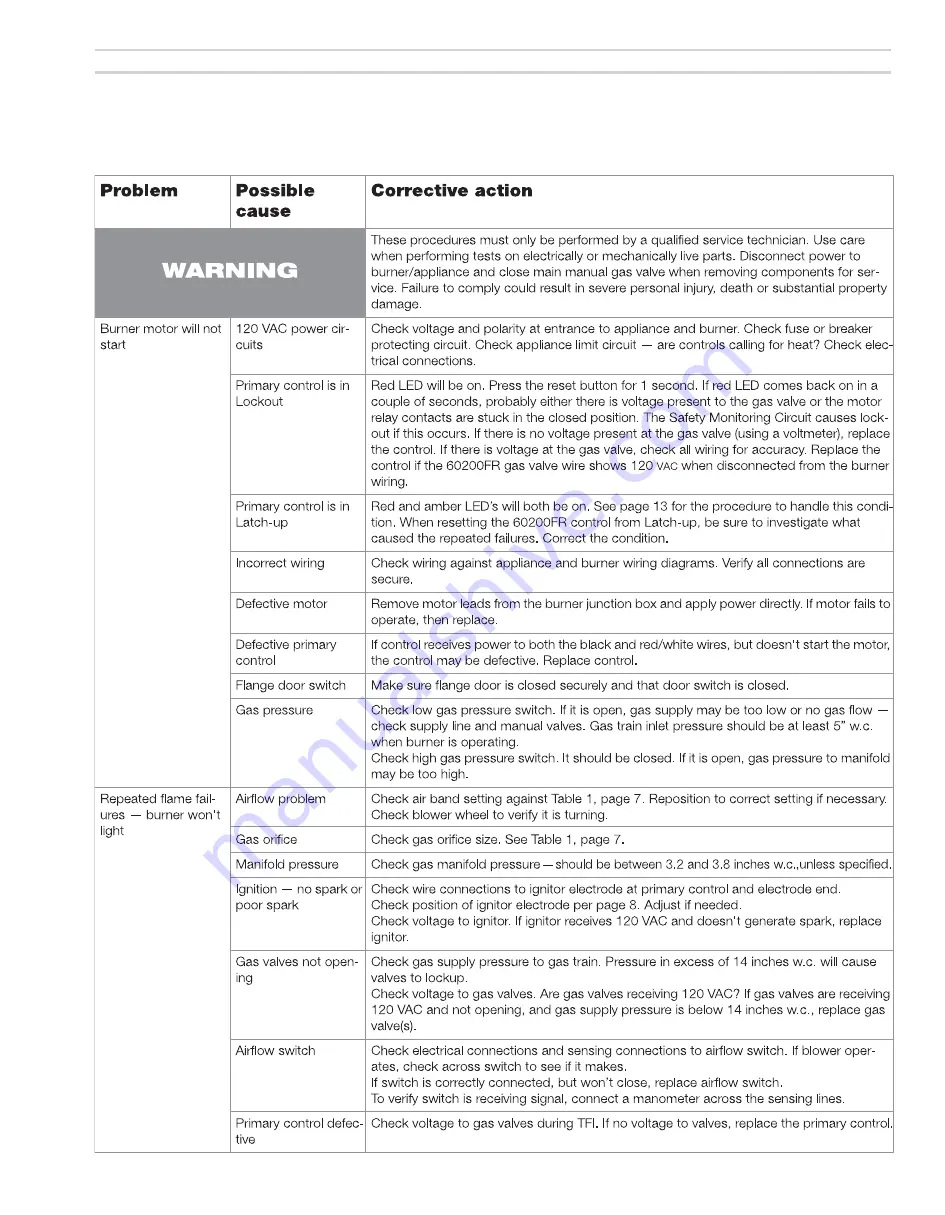
7.  Troubleshooting

Содержание 301GAS

Страница 1: ...el 60200FR microprocessor control Agencies UL Listed Installer servicer Except where specifically stated other wise this manual must be used only by a qualified service technician In the state of Mass...

Страница 2: ...nually for start up and burner appliance service When servicing the burner Disconnect electrical supply to burner before attempting to service to avoid electrical shock or possible injury from moving...

Страница 3: ...ge omitted for clarity with powder coat paint finish 15 Flame rod insulator assembly 16 Combustion head 17 Gas saddle connection gasket 18 Gas manifold 19 Ignition electrode insulator assembly 20 Stat...

Страница 4: ...chimney that has one or more sides exposed to the outside Install a listed stainless steel liner to vent the flue products A defective vent system could result in severe personal injury death or subst...

Страница 5: ...iance instruction manual when available to size combustion air openings Use the following guidelines when appliance instructions are not available All air from inside building building must be well ve...

Страница 6: ...amic fiber or Fiberglass insulation Ceramic fiber materials such as chamber liners may contain carcinogenic particles chrystobalites after exposure to heat Airborne particles from fiberglass or cerami...

Страница 7: ...ner does not comply with the specifications of Table 1 and other guidelines in this manual Combustion head air tube configurations 301GAS burners are supplied with either an B or C head and air tube c...

Страница 8: ...g b Close the manual gas valve on the gas supply line c Disconnect the burner gas train union d Remove the gas pipe at the burner air tube e Remove the four nuts securing the burner hinged door flange...

Страница 9: ...x a Match wire colors of the incoming wires to those pre wired to the terminal strip inside the gas train J box b See the label in the burner junction box or the wiring diagram on page 11 Gas valve ve...

Страница 10: ...supply pressure 14 inches w c Minimum supply pressure 5 inches w c Do not expose the gas train to gas pressure in excess of 14 inches water column Higher pressure could damage the valve seat resultin...

Страница 11: ...hite wires are from the 120 vac HOT side and that the power is no less than 102 vac nor more than 132 vac Checking burner flame signal The 60200FR uses flame rectification to detect the flame Because...

Страница 12: ...oap suds mixture to all gas piping joints near burner and check for any leaks If any leaks appear repair before proceeding Figure 12 Air band adjustment and retest Set burner air band See Figure 12 Lo...

Страница 13: ...e control will restart Releasing the button before the LED s turn off will cause the control to remain in latch up The 60200FR control will not reset from lockout or latch up if power is interrupted P...

Страница 14: ...firing rate Preparation before checkout Burner appliance installed per appliance instruction manual Burner components verified against Table 1 page 7 Burner appliance installed per all applicable cod...

Страница 15: ...pressure switch to a pressure less than actual manifold pressure The high gas pressure switch should shut the burner down Replace the switch if necessary Turn off power to the appliance burner remove...

Страница 16: ...ng studs Perform the complete checkout procedures of pages 12 through 15 including system inspection and checks 6 Maintenance and service procedures Maintenance service procedures Cleaning blower whee...

Страница 17: ...Model 301GAS burner Instruction manual Carlin part number MN301GAS Rev 11 24 14 17 Where appliance instructions differ from this manual follow the appliance instructions 7 Troubleshooting...

Страница 18: ...mary voltage to ignitor If ignitor receives 120 VAC and doesn t generate spark replace ignitor Airflow Check air band setting against Table 1 page 7 Wrong orifice size Verify orifice size per Table 1...

Страница 19: ...flange burner verify the insertion depth on the appliance and burner see page 7 If using the adjustable flange Figure 14 measure the appliance inser tion depth to the set the position of the flange on...

Страница 20: ...augmenter NA 5 Air band four slot 47001S 6 Air shutter low input range B head tube Air shutter mid input range C head tube 99254 99278 7 Blower wheel 5 diameter x 4 deep 28563S 8 Motor Carlin PSC 1 6...

Страница 21: ...al follow the appliance instructions 9 Replacement parts Burner continued 1 2 3 4 5 6 7 8 9 10 11 12 13 14 15 16 17 18 Set screws Burnerisshownwithweldedflange suppliedonlyonburners ordered for specif...

Страница 22: ...box 99517 7 Primary gas valve Honeywell V48A 1 NPT Bleed restrictor fixed 99227 99228 8 Pipe nipple schedule 40 steel 1 NPT x 4 long Obtain locally 9 Pipe nipple schedule 40 steel 1 NPT x 2 long Obta...

Страница 23: ...301GAS burner Instruction manual Carlin part number MN301GAS Rev 11 24 14 23 Where appliance instructions differ from this manual follow the appliance instructions 9 Replacement parts Gas train conti...

Страница 24: ...Model 301GAS burner Instruction manual Carlin part number MN301GAS Rev 11 24 14 24 Where appliance instructions differ from this manual follow the appliance instructions...

Отзывы: