8200-M554-O1
x
2XX-EIP
Page 3
INSTALLATION, CONT.
Cable Installation in the Indicator
1. Loosen an unused cable gland connector for the cable.
2. Insert the Ethernet cable (CAT 5 or equivalent) through the gland connector and into the
enclosure.
3. Consult your network administrator for the proper procedure to terminate the cable.
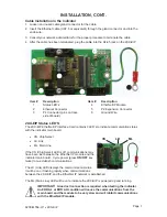
4. After the cable has been terminated, plug the cable into the RJ-45 jack on the 2XX-EIP.
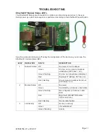
Item #
Description
Item #
Description
1
Status LED’s
4
EtherNet/IP Module
2
Ethernet Connector
5
P2 Expansion Connector
3
P4 Connector (pins on trace
side of board)
6
Ground Wire
2XX-EIP Status LED’S
The 2XX-EIP EtherNet/IP Interface Card contains 3 LED’s to indicate communication status
with the indicator main board.
x
CS, Chip Select
x
LK,
Link
x
ML,
Main
Line
If the CS (Chip Select) LED is off, communications may
have been lost between the EtherNet IP module and the
indicator main board. Cycle power (press
ON/OFF
key
twice) to re-establish communications.
The LK (Link) LED displays the communication status.
It will be on or flashing rapidly when communications
between the 2XX-EIP and the EtherNet IP network is established.
The ML (Main Line) LED will be on to indicate the 2XX-EIP is powered up and running.
IMPORTANT! A load cell connection is required when testing the indicator.
An ERR AL or ERR AH condition will cause the communications from the
main board and the module to be very slow and will inhibit communications
with the EtherNet/IP module.
c
c
g
g
d
d
e
e
f
f
CS
ML
LK
h
Содержание 2XX-EIP
Страница 2: ...8200 M554 O1 x 2XX EIP Page 2...
Страница 14: ...2...
Страница 15: ...8200 M554 O1 x 2XX EIP Page 12 2XX EIP ADDENDUM For 225 Indicator...
Страница 19: ...2...
Страница 20: ...2...


