background image

17

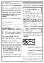
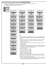
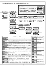
“PROG/OK” to set

“PROG/OK” to confirm

BACK TO MOTION MENU

DIST. FROM OPEN

(5)

0...9 steps 

EXIT

OK

SEQUENTIAL COM. 

OPEN-SHUT/

OPEN-STOP-SHUT

“PROG/OK” to set

AUTO-RECLOSING

ON/OFF

“PROG/OK” to set

“PROG/OK” to set

WARNING LIGHTS

FIXED/

INTERMITTENT

“PROG/OK” to set

INDICATOR LIGHT


(1)

FIXED/

INTERMITTENT

“PROG/OK” to set

PHOTOCELL INVERT 

(2)

DURING CLOSING/

AND IN STOP

“PROG/OK” to set

“PROG/OK” to set

“PROG/OK” to set

“PROG/OK” to set

LC/CH2 OUTPUT

RADIO CHANNEL/

COURTESY LIGHT

“PROG/OK” to set

“PROG/OK” to confirm

BACK TO OPTIONS

PRE-FLASHING

ON/OFF

TEST FI 

(3)

ON/OFF

TEST FS 

(3)

ON/OFF

MEMO RADIO

ON/OFF

EXIT

OK

“PROG/OK” to set

FI CONTACT

NC/8K2

TB CONTACT

NC/8K2

“PROG/OK” to set

“PROG/OK” to set

“PROG/OK” to set

“PROG/OK” to confirm

BACK TO SAFETY DEVICES

FS CONTACT

NC/8K2

CP CONTACT

NC/8K2

EXIT

OK

“PROG/OK” to set

CURRENT SENSOR 

(4)

LEVELS 1...5

“PROG/OK” to set

“PROG/OK” to set

LIMITED OPENING

1...9 meters

“PROG/OK” to set

ADJUST CONTRAST

0...63

CONTRAST

OK

“PROG/OK” to confirm

“PROG/OK” to confirm

SAFETY DEVICES

OK

“PROG/OK” to confirm

CANCELLATION

OK

MEMORISE

OK

“PROG/OK” to confirm

“PROG/OK” to confirm

“PROG/OK” to confirm

“PROG/OK” to confirm

BACK TO RADIO CODES MENU

CLEAR ALL MEMORY

OK

CHANNEL FUNCTION

OK

EXIT

OK

“PROG/OK” to confirm

REMOTE

OK

OPTIONS

OK

“PROG/OK” to confirm

MOTION

OK

PRESS ANY KEY

BACK TO TEST MENU

“PROG/OK” to confirm

TEST

OK

“PROG/OK” to confirm

DISPLAY

OK

“PROG/OK” to confirm

“PROG/OK” to set

“PROG/OK” to confirm

BACK TO DISPLAY MENU

EXIT

OK

REAR LIGHTING

ALWAYS ON/

60 SEC./30 SEC.

TORQUE SELECTION

LEVELS 1...2

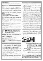
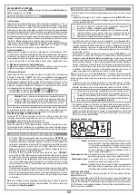
PROGRAM

T B

F S

F I

CP

00.000.001

T B

F S

F I

CP

TEST

T B

F S

F I

CP

PRESS the 

transmitter 

channel to be 

memorised

CANCELLING.....

MEMORISE [nr ...]

Activation 1

PRESS the 

transmitter 

channel to be 

memorised

MEMORISE [nr ...]

Activation  2

MEMORISE [nr ...]

CODE MEMORISED

“PROG/OK” to confIrm

CLEAR ALL MEMORY?

OK

PRESS the 

transmitter 

channel to be 

cancelled

CANCEL [nr ...]

Activation 1

PRESS the 

transmitter 

channel to be 

cancelled

CANCEL [nr ...]

Activation  2

CANCEL [nr ...]

CODE CANCELLED

Exit

“PROG/OK” to set

CHANNEL A

COMMAND TD/TAL/TA/TC/

STOP/NO COMMAND

CHANNEL B

COMMAND TD/TAL/TA/TC/

STOP/ NO COMMAND

“PROG/OK” to set

“PROG/OK” to set

CHANNEL C

COMMAND TD/TAL/TA/TC/

STOP/ NO COMMAND

“PROG/OK” to set

CHANNEL D

COMMAND TD/TAL/TA/TC/

STOP/ NO COMMAND

“PROG/OK” to set

 BACK TO CHANNEL FUNCTION MENU

EXIT

OK

OUT OF POS

T B

F S

F I

CP

STOP PROG

T B

F S

F I

CP

PROGRAM

T B

F S

F I

CP

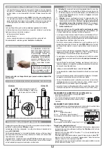
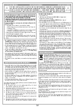
Flashing on the display. You have to enter the programming mode to program the system,

During normal operation it indicates that the "automatic repositioning" procedure is about to take place. In 

this case any commands received (TA, TC, TAL or TD) will automatically start this procedure.

This happens when an N.C. contact is activated (FI, FS, CP) during encoder programming or automatic 

repositioning.  Once  the  passive state  of  the  security  devices has  been reset  the  gate  will  start  moving 

again automatically. It also happens if a blackout occurs during programming.

Safety device test error. Check the condition of the safety devices and make sure that the alarm cuts in 

when an obstacle interferes with the beam (the relative LED will switch off). In case of anomalies replace 

the damaged safety device or bridge the contact and deactivate the safety test  (option menu).

This occurs when  the  programmer  sends  a  command  to  the  motor  and  nothing happens  (the  motor 

doesn't move). Check the motor faston connections and the condition of the fuses "F2", "F3" and then 

give another  opening  or  closing  command.  If the  motor  still  doesn't  move  you  are  faced  with either  a 

mechanical problem or a problem with the programmer. 

If this error occurs during normal motor operation it means that there is a problem with one of the encoder 

signals. Check the relative connections and carry out automatic repositioning. 

The  gate  movement  direction is  different  from the encoder setting  (eg.  the  gate moves in  the  closing 

direction while  the  program is  carrying  out  the  opening  stage). Check the motor power  supply 

connections.

Current sensor error. When the gate is not moving this symbol means there is a problem with the current 

sensor.

When the  safety edge intervenes the gate will automatically invert for a few moments, both in the closing 

as well  as the  opening direction,  to  free  the  obstacle  it will  then stop  for  3  minutes and then  continue 

moving in the original direction after a 10 second preflashing period has elapsed.

When the sensor intervenes the gate will automatically invert for a few moments, both in the closing as 

well as the opening direction, to free the obstacle it will then stop for 3 minutes and then continue moving 

in the original direction after a 10 second preflashing period has elapsed.

SAFETY ERR

T B

F S

F I

CP

ERROR MOT1

T B

F S

F I

CP

ERROR ENC1

T B

F S

F I

CP

ERROR DIR1

T B

F S

F I

CP

Alarm indications

AUTO PROG

T B

F S

F I

CP

OPENING

T B

F S

F I

CP

PAUSE

T B

F S

F I

CP

Pause time programming or 

pause for automatic reclosing 

(if activated)

Automatic programming under 

way

Opening stage

Block during opening  

Closing stage

Block during closing   

Current sensor updating (only 

during programming)

Test mode

Battery mode with a fully 

charged battery

Battery mode with a 

discharged battery. The motor 

and commands will be 

blocked.

STOP OPEN

T B

F S

F I

CP

UPDAT.SNS1

T B

F S

F I

CP

Operational indications

CLOSING

T B

F S

F I

CP

STOP CLOSE

T B

F S

F I

CP

AUTO PROG

ERR. SENS1

T B

F S

I

C P

ACT. EDGE

T B

F S

I

C P

ACT. SENS

T B

F S

I

C P

    TEST

T B

F S

I

C P

BATT. 

[99%]

T B

F S

I

C P

BATT. 

[0%]

T B

F S

I

C P

F

F

F

F

F

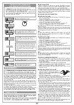
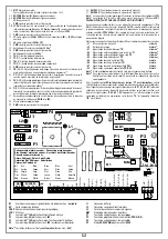
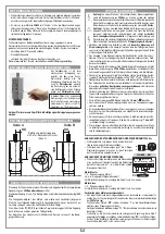
•  If you have safety devices working with 8.2k

 contacts select the correct setting from the safety device menu.

Language choice:

•  Press the right and left buttons simultaneously to enter 

the language submenu.

•  Press the right and left buttons to change the language: 

Italiano - English - Français - Deutsch - Español.

•  Press the "PROG/OK" button to confirm the choice.

“PROG/OK” to confirm

ENGLISH

OK

Press the right and left buttons

 simltaneously to enter the 

language submenu

PROGRAM

T B

F S

F I

C P

Содержание 305/GLi824

Страница 1: ...n cuidado Advertencias importantes Página 37 Desbloqueo del motorreductor Página 38 Programador electrónico Página 38 Conexión eléctrica Páginas 38 39 Esquema eléctrico Página 39 Procedimiento de programación Páginas 40 41 Reposicionamiento Página 42 Mando por radio Página 42 Modo de funcionamiento Página 43 Apertura limitada peatonal Página 43 Mando por batería Página 43 Características técnicas ...

Страница 2: ...2 NOTES ...

Страница 3: ...Ω 8 Commutateur du mur TB TD 9 Boîte de dérivation 10 Interrupteur omnipolaire avec ouverture des contacts d au moins 3 mm 11 Câble d alimentation principale 230 Vac 12 Chemin pour branchement basse tension 13 Prise d air Attention le schéma diffusé à titre purement indicatif est destiné à vous aiderdanslechoixdescomposantsélectroniquesCardinàutiliser Parconsé quent il n a aucune valeur obligatoir...

Страница 4: ... TAL N O LP LS OUT 24Vdc 9 10 11 12 13 14 15 16 17 18 19 20 21 22 23 24 25 26 LC CH2 L2 CSER 31 30 29 CMN EMRG 1 EMRG 2 Bl Blu Blue Bleu Blau Azul Gr Verde Green Vert Grün Verde Gy Grigio Grey Gris Grau Gris Yw Giallo Yellow Jaune Gelb Amarillo Wh Bianco White Blanc Weiss Blanco Collegamento motore encoder Connecting motor encoder Branchement moteur encodeur Anschluss der Motor Encoder Conexionado...

Страница 5: ...grati Il motoriduttore è alimentato con tensione max 24 Vdc Al suo interno opera un sistema cinematico a doppia riduzione che lavora in bagno di grasso fluido permanente Ilmotoriduttoreèdotatodiunsistemadisbloccointegratoperl attivazione della reversibilità del riduttore epicicloidale Il collegamento tra il motoriduttore e la centrale avviene tramite un cavo a 6 a poli Programmatore è destinato al...

Страница 6: ...a COLLEGAMENTI ALIMENTAZIONE CENTRALINA 230 Vac Collegare i fili di comando e quelli provenienti dalle sicurezze Portare l alimentazione generale alla morsettiera separata a due vie che è già collegata al primario del trasformatore COLLEGAMENTI MOTORI ENCODER Rispettare scrupolosamente la sequenza di connessione dei motori alla centralina l ordine dei morsetti 1 6 è identico sul motore e sulla cen...

Страница 7: ...er manovra di emergenza 1 31 EMRG2 N A ingresso pulsante per manovra di emergenza 2 Nota 1 La somma delle due uscite per carichi esterni non deve superare 10W Nota 2 La selezione N C 8 2 kΩ viene effettuata mediante menu sul display LCD1 TUTTI I CONTATTI N C NON UTILIZZATI VANNO PONTICELLATI Diconseguenzaitestsullesicurezzecorrispondenti FI FS devonoesseredisabilitati Se si vuole attivare il test ...

Страница 8: ...er navigare all interno dei menù e o per la regolazione del contrasto del display utilizzare PROG OK per modificare l impostazione del parametro scelto e o per dare conferma Note 1 La lampada spia lampeggia lentamente durante l apertura velocemente durante la chiu sura resta accesa quando la porta è bloccata non completamente chiusa ed è spenta quando la porta è completamente chiusa 2 Modalità FI ...

Страница 9: ... apertura in modo da liberare l ostacolo poi rimane ferma per 3 minuti e trascorso questo lasso di tempo riprende il moto nella direzione in cui era stato interrotto dopo aver effettuato un prelampeggio di 10 secondi Quando interviene il sensore l anta inverte immediatamente il moto per qualche istante sia in chiusura che in apertura in modo da liberare l ostacolo poi rimane ferma per 3 minuti e t...

Страница 10: ...ip di mezzo secondo dopodiché il ricevitore sarà pronto a memorizzare un altro codice 4 Per uscire dalla modalità lasciare trascorrere 3 sec senza memorizzare codici Il ricevitore emetterà un bip della durata di 5 sec ed uscirà dalla modalità Nota Quando la memoria viene completamente occupata il buzzer emetterà 10 bip ravvicinati uscendo automaticamente dalla modalità di memorizzazione via radio ...

Страница 11: ...apertura della porta è selezionabile da 1 a 9 metri modificando il parametro Apertura Limitata Il dispositivo permette il funzionamento del sistema anche in assenza di rete Il programmatore dispone di un circuito di carica per batteria NiMH a 24V gestito da un microcontrollore dedicato che regola la tensione in relazione allo stato della batteria innestato tramite connettore Per evitare il rischio...

Страница 12: ...12 NOTES ...

Страница 13: ...SCRIPTION The set consists of 2 geared motors 300 GLi824 with an incorporated encoder without onboard electronics 1 electronic programmer CCi924 with NiMH batteries a battery charger and an integrated S449 radio frequency module The geared motor is powered by 24 Vdc and is fitted with a double reduction kinetics system immersed in permanently fluid grease The emergency manoeuvre is carried out by ...

Страница 14: ...ewiresintothebindingpostsrigorouslyrespectingtheorderofthecolours indicated in figure 4 and tighten down the cable clamp PC for the slave motor just connect the 24 V power supply wires to change the motor s rotating direction invert cables 1 and 2 INSTRUCTIONS FOR USE N L IMPORTANT REMARKS ELECTRONIC PROGRAMMER This device has been created to be integrated into the structure of specially made coun...

Страница 15: ...ulsante per manovra di emergenza 1 31 EMRG2 N A ingresso pulsante per manovra di emergenza 2 Note 1 The total of the 2 external device outputs must not exceed 10W Note 2 The N C 8 2 kΩ selection is carried out on the LCD1 display ALL UNUSED NC CONTACTS MUST BE JUMPED and consequently the corre sponding security device tests FI FS must also be deactivated If you want to activate the FI FS test both...

Страница 16: ...when the door is completely closed 2 FI Mode FI also active when the door is blocked If the photocells are in alarm and the door is blocked no movement commands will be accepted even opening commands FI active only during closing In both cases activating the FI safety device during the closing stage will force travel direction inversion 3 Photocell test FI FS Ifyouenablethesecuritytestyouwillhavet...

Страница 17: ...mechanical problem or a problem with the programmer If this error occurs during normal motor operation it means that there is a problem with one of the encoder signals Check the relative connections and carry out automatic repositioning The gate movement direction is different from the encoder setting eg the gate moves in the closing direction while the program is carrying out the opening stage Ch...

Страница 18: ...e 4 To leave the programming mode wait for 3 seconds without pressing any buttons The receiver will sound a five second long beep and will then exit the program ming mode Note When the memory is entirely occupied the buzzer will sound 10 rapid beeps and will automatically leave the programming via radio mode The same signal is given each time you try to enter programming via radio when the memory ...

Страница 19: ...t is managed by a dedicated micro controller The control chip adjusts the voltage according to the condition of the connected battery To avoid the risk of overheating only use the battery supplied by the manufacturer SPN 999540 If the battery shows signs of damage it must be replaced immediately The battery must only be installed removed by qualified personnel Used batteries must not be thrown int...

Страница 20: ...20 NOTES ...

Страница 21: ...menté avec une tension maxi 24 Vdc Au sein de celui ci intervientunsystèmecinématiqueàdoubleréductionquiopèresousbaindegraisse fluide Lemotoréducteurestéquipéd unsystèmededéverrouillageàcâblepourl activation de la réversibilité du réducteur épicycloïdal Le branchement entre motoréducteur et armoire de commande s effectue par l intermédiaire d un câble blindé particulier à 6 pôles à connexions rapi...

Страница 22: ...n devra bloquer tant l isolation que le conducteur il suffit d un collier BRANCHEMENT DE L ALIMENTATION DE LA CENTRALE 230 Vac Brancher les fils de commande et ceux qui proviennent des dispositifs de sécurité Tirer l alimentation générale jusqu au bornier séparé à deux voies qui est déjà branché au primaire du trans formateur BRANCHEMENT DU MOTEUR ENCODEUR Respecterrigoureusementlaséquencedeconnex...

Страница 23: ...e 2 Nota 1 La somme des 2 sorties pour dispositifs externes ne doit pas être supérieure à 10W Nota 2 La sélection N C 8 2 kΩ s effectue au moyen du menu sur l afficheur LCD1 FAIRE UN PONT SUR TOUS LES CONTACTS N F INUTILISÉS En conséquence invalider les tests sur les dispositifs de sécurité correspondants FI et FS Si l on désire activer le test sur les dispositifs FI et FS la partie émettrice tout...

Страница 24: ...les menus et ou pour régler le contraste de l afficheur utiliser PROG OK pour modifier le paramètre sélectionné et ou pour le confirmer Nota 1 La lampe témoin clignote lentement pendant l ouverture et rapidement pendant la fermeture elle reste allumée quand la porte est verrouillé en position de fermeture incomplète et est éteinte quand la porte est complètement fermé 2 Mode de fonctionnement FI F...

Страница 25: ... ait un problème mécanique au niveau du moteur ou un problème de logiciel sur la centrale Erreur de comptage de l encodeur Si ceci se produit pendant l utilisation normale du moteur il y a un problème sur les signaux inhérents à l encodeur vérifier les relatives connexions et lancer le repositionnement automatique Erreur de direction de l encodeur Le sens de marche du portail est différent de celu...

Страница 26: ...e Après quoi le récepteur sera prêt à mémoriser un autre code 4 Pourquitterleprocédédemémorisation laisserpasser3secondessansmémoriser decodes L avertisseursonoreémettraunbipde5secondesetsortiraduprocédé Nota lorsque la mémoire est pleine l avertisseur sonore émet 10 bips très courts et on sort automatiquement du procédé de mémorisation via radio Cette signali sation s obtiendra également chaque f...

Страница 27: ...ent sur la distance qu il a parcourue en fermeture Nota lacommanded ouverturepartiellepeutaussiêtredélivréeenutilisantladeuxième fonctionradio L ouverturedelaporteestsélectionnablede1à9mètresenintervenant sur le paramètre Ouverture partielle Le dispositif permet le fonctionnement du groupe opérateur même en cas de coupure de courant Leprogrammateurdisposed uncircuitdechargepourbatteriesNiMHà24V en...

Страница 28: ...28 NOTES ...

Страница 29: ...n Steuerung CCi9242 mit NiMH Batterien integrier tem Batterieladegerät und Funkmodul Der Getriebemotor wird mit einer Spannung von max 24 Vdc gespeist In seinemInnerenarbeiteteinkinematischesSystemmitdoppelterUntersetzung Der Getriebemotor ist mit einem integrierten Entriegelungssystem für die Akti vierung der Umsteuerbarkeit des Planetengetriebes ausgerüstet Der Anschluss zwischen Getriebemotor u...

Страница 30: ... einem Kontaktenabstand von mindestens 3 mm zwischenge schaltet werden Keine Leitungen mit Aluminiumleiter verwenden in die Klemmleiste einzufüh rende Kabelenden nicht verzinnen Kabel mit der Markierung T min 85 C wetterbeständig verwenden Die Leitungen müssen in der Nähe der Klemmleiste in angemessener Weise so befestigt werden dass sowohl die Isolierung als auch der Leiter befestigt wird Kabelba...

Страница 31: ... diese mit einem Koaxialkabel RG58 Imp 50Ω anschließen 28 Aussenleiter Funkempfängerantenne 29 CMN Neutralleiter für Notbetätigungstasten 27 EMRG2 N O Kontakt Eingang Notbetätigungstaste 2 28 EMRG1 N O Kontakt Eingang Notbetätigungstaste 1 B1 Summer Signalisierung Funk Modus BC Karte Batterieladegerät CSER Serieller Anschluss nur für Diagnostik LCD1 Display F1 Flach Steck Sicherung 4 15A Motorstro...

Страница 32: ... des Kontrasts im Display die Pfeile benutzen PROG OK für die Änderung der Einstellung des ausgewählten Parameters und oder für die Bestätigung benutzen Anmerkung 1 Die Kontrollleuchte blinkt langsam während der Öffnung schnell während der Schließung leuchtet ohne Unterbrechung wenn das Tor bei nicht vollständiger Schließung blockiert ist und erlischt wenn das Tor vollständig geschlossen ist 2 Bet...

Страница 33: ...ben Wenn der Motor auch jetzt nicht anläuft könnte das Problem bei der Mechanik des Motors oder bei der Steuereinheit liegen Wenn dies bei der normalen Verwendung des Motors auftritt bedeutet dies dass ein Problem mit der Encoder Signalen besteht Die Anschlüsse überprüfen und die automatische Rückstellung ausführen Die Laufrichtung des Torflügels ist anders als wie vom Encoder festgelegt z B Das S...

Страница 34: ...einen Code zu speichern ver streichen lassen Der Empfänger gibt einen 5 Sekunden dauernden Bip Ton von sich und verlässt den Speichermodus Anmerkung Wenn der Speicher voll ist gibt der Summer zehn schnell aufeinan derfolgende Bip Töne von sich und beendet automatisch den funkgesteuerten Speichermodus Das Gleiche geschieht auch bei jedem Versuch sich bei vollem Speicher in den funkgesteuerten Speic...

Страница 35: ...werden Das Öffnen des Tors kann ausgewählt werden von 1 bis 9 Meter über die Änderung des Parameters Begrenzte Öffnung Die Vorrichtung erlaubt den Betrieb des Systems auch bei fehlender Netzversor gung Die Steuerung verfügt über einen Ladekreis für NiMH Batterien auf 24V der gesteuertwirdvoneinemeigenenMikrocontroller derdieSpannungabhängigvom Zustand der Batterie regelt Der Ladekreis wird über ei...

Страница 36: ...36 NOTES ...

Страница 37: ...rónico CCi924 con baterías NiMH cargador de baterías y módulo radio S449 incorporados El motorreductor está alimentado con tensión máx de 24 Vdc En su interior actúa un sistema cinemático de doble reducción que trabaja en baño de grasa fluida permanente El motorreductor está provisto de un sistema de desbloqueo integrado para activar la reversibilidad del reductor epicicloidal La conexión entre el...

Страница 38: ...IONADOS ALIMENTACIÓN CENTRALITA 230 Vac Conectar los cables de control y los procedentes de los dispositivos de seguridad Llevar la alimentación general a la placa de bornes separada por dos tornillos de dos vías que ya está conectada con el primario del transformador CONEXIONADOS MOTORES ENCODER Respetar estrictamente la secuencia de conexionado de los motores con la centralita la secuencia de lo...

Страница 39: ...2 Nota 1 la suma de las dos salidas para cargas exteriores no debe exceder de 10W Nota 2 La selección N C 8 2 kΩ se efectúa mediante menú en el display LCD1 TODOS LOS CONTACTOS N C QUE NO SE UTILICEN DEBEN PUENTEARSE y en consecuencia deben deshabilitarse los test en los dispositivos de seguridad correspondientes FI y FS Si se habilita el test en FI y FS tanto la parte emisora como la parte recept...

Страница 40: ...en los menús y o para regular el contraste del display utilizar PROG OK para modificar la configuración del parámetro seleccionado y o para confirmar Notas 1 Laluztestigosevuelveintermitentelentamentedurantelaapertura rápidamentedurante el cierre permanece encendida cuando la puerta se bloquea en posición no totalmente cerrada y se apaga cuando la puerta está totalmente cerrada 2 Modalidad FI FI a...

Страница 41: ...ste error se visualiza cuando se proporciona un control con el motor desbloqueado Si se verifica durante la utilización corriente del motor significa que existe un problema en las señales correspondientes al encoder comprobar los conexionados correspondientes y realizar el reposicionamiento automático El sentido de marcha de la cancilla es diferente del establecido por el encoder ejemplo la cancil...

Страница 42: ... a continuación el receptor estará listo para memorizar otro código 4 Parasalirdelamodalidad esperar3segundossinmemorizarcódigos Elreceptor emitirá un bip de 5 segundos de duración y saldrá de la modalidad Nota cuando la memoria ha sido ocupada por completo el avisador acústico emitirá 10 bips uno tras otro saliendo automáticamente de la modalidad de memorización vía radio La misma indicación se o...

Страница 43: ...rta Nota el mando de apertura limitada puede darse usando también la segunda función radio La apertura de la puerta puede seleccionarse de 1 a 9 metros modificando el parámetro Apertura Limitada Eldispositivopermiteelfuncionamientodelsistematambiéncuandofaltalacorriente El programador dispone de un circuito de carga para batería NiMH a 24V diri gido por un microcontrolador dedicado que regula la t...

Страница 44: ...tura de funcionamiento C 20 55 Potencia en salida para 1 o 2 motores W 60 60 Grado de protección IP 55 Aparato de clase II Cls Receptor incorporado Frecuencia de recepción S449 MHz 433 92 Número de canales N 4 Número de funciones gobernables N 2 Número de códigos almacenables N 300 Technische Daten des Antriebs Stromversorgung Vdc 24 Nennstrom A 2 Aufnahmeleistung W 50 Einschaltdauer 70 Getriebsge...

Отзывы: