background image

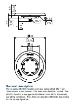
General description

The supplied SENSORswitch can have options that differ from

those shown in this manual. This does not affect the function. The

SENSORswitch is equipped with different color LEDs to indicate

operating conditions. The LEDs are actuated differently depending

on the pin configuration.

Содержание CHT3 Series

Страница 1: ...CHT3 Original Operating Instructions CHT3 1 CHT3 2 CHT3 A CHT3 V CHT3 N CHT3 S CHT3 Original Operating Instructions CHT3 1 CHT3 2 CHT3 A CHT3 V CHT3 N CHT3 S...

Страница 2: ...ifications 6 Connection options 6 Connection plan 8 Drilling pattern 9 Dimensional drawing 10 General description 11 Assembly 12 Recommended screw types 13 Maximum dimensions of the screws 13 Maintena...

Страница 3: ...lectrician according to the applicable electrotechnical regulations The safety of the system in which the SENSORswitch is integrated is the responsibility of the operator Notes and symbols used Warnin...

Страница 4: ...ymbol next to the warning indicates the type and source of the danger NOTICE Notice designates a situation which may cause material damages and impair the product s function if attention is not paid T...

Страница 5: ...and experience as well as knowledge of relevant standards who can evaluate the work assigned to them correspondingly and recognize potential risks Intended use The SENSORswitch is intended for use in...

Страница 6: ...e drop max 3 V at 400 mA Power consumption at 24 V with signal tone with vibration with signal tone and vibration max 30 mA max 70 mA max 130 mA max 200 mA Operating temperature dynamic static 30 C 22...

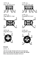
Страница 7: ...pin CHT3 _1_ Plug AMP 6 3 4 pin CHT3 _4_ Plug AMP 6 3 4 pin CHT3 _8_ Plug M12 4 pin CHT3 _8_ Plug M12 5 pin Strands CHT3 _7_ 200 mm single strands with wire end ferrules Wire end ferrules with plastic...

Страница 8: ...ED1 PNP NO 0V 3 4 2 1 LED1 LED2 brown white black blue Load NPN NO 4 pin VDC 0V LED1 NPN NO 0V 3 2 4 1 load LED1 LED2 brown black white blue PNP NO 5 pin LED1 LED2 VDC LED1 VDC LED2 PNP NO 0V VDC 3 4...

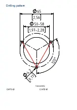
Страница 9: ...Drilling pattern V assembly CHT3 2 CHT3 V...

Страница 10: ...A assembly CHT3 1 CHT3 S CHT3 N CHT3 A Dimensional drawing Exemplary presentation plug M8 4 pin...

Страница 11: ...have options that differ from those shown in this manual This does not affect the function The SENSORswitch is equipped with different color LEDs to indicate operating conditions The LEDs are actuate...

Страница 12: ...ly align centered and vertically and mark holes C Select the diameter of the holes according to the recommended screw type and start drilling Connect the SENSORswitch B electrically according to the c...

Страница 13: ...O 7045 M4 DIN EN ISO 1481 3 9 mm DIN EN ISO 7049 3 9 mm Maximum dimensions of the screws The drawing shows the maximum dimensions of the screws Maintenance Maintenance operations Carry out the followi...

Страница 14: ...the SENSORswitch for cleaning to prevent unintentional actuation NOTICE Solvents contained in cleaning agents can attack the plastic of the button 4Clean the surface of the button with a neutral clean...

Страница 15: ...s must be complied with Options Braille characters Relief Color variations RAL 1023 RAL 7035 RAL 9017 RAL 3020 RAL 5017 RAL6024 Scan QR code for more information or visit our website cht3 captron de M...

Страница 16: ...perating instructions have been authored and published by CAPTRON Electronic GmbH Johann G Gutenberg Stra e 7 82140 Olching Germany Tel 49 0 8142 44 88 160 sales captron com www captron com Copyright...

Страница 17: ...Product description Product description Product description Product description...

Отзывы: