ZR70 MC A, ZR65 MC A, ZR60 A
CHAPTER 1. GENERAL DESCRIPTION OF PRODUCT
1-76
7-13 AV Insert (Not available on PAL Models)
In AV Insert mode, an ITI (Insert and Track Information) area is kept and audio, video, and sub-codes are overwritten.
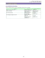
7-13-1 Tapes Allowing AV Insert
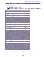
Only tapes with SP recording can be used with AV Insert mode. If an attempt is made to enter AV Insert mode with any other type
of tape, the camcorder switches to Stop mode. The camcorder stops (and displays a warning) if LP mode is detected, or if no
recording SDL is detected.
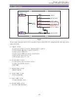
7-13-2 AV Insert Signal Input Source Selection
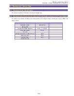
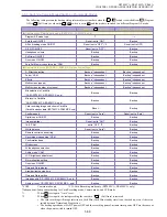
The input source is selected automatically according to the following order of priority:
DV terminal (ACK detected) > AV terminal detected > No connection
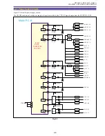
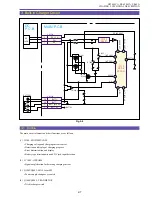
The settings for line video output are as follows.
(1) When DV terminal input is used : The S terminal and AV terminal are set to Output mode. The speaker output can be monitored.
(2) When AV terminal input is used : The S terminal and AV terminal are set to Input mode. The speaker output can be monitored.
(3) When there is no connection
: The S terminal and AV terminal are OFF. The speaker output is muted.
7-13-3 AV Insert Procedure
(1) In VCR mode, play and pause the tape at the position where you want to insert AV. Next, press the [AV Insert] button on the remote
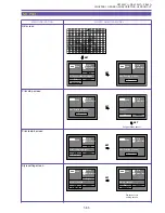
control. The camcorder switches to AV Insert mode (AV Insert pause), and “
” (AV Insert pause) is displayed on the LCD panel
(CVF).
(2) Push the Pause [ ] button and input the video and audio.
This starts the AV insertion process.
●
(AV Insert) is displayed on the LCD panel (CVF).
(3) When you want to stop, press the Stop [
■
] button.
AV Insert mode ends and the AV Insert display disappears. The camcorder is stopped.
•
You can press the Pause [ ] button instead of the Stop [
■
] button to return to the condition in step (1) (AV Insert pause) without
exiting AV Insert mode.
•
Another way to exit AV Insert mode is to press the [AV Insert] button on the remote control during AV Insert pause.
•
If the [Zero Set Memory] button on the remote control is pressed in advance at the tape position where you want AV insertion to
end, then after step (2), the camcorder will automatically stop at the set position and AV insertion will end.
7-13-4 CGMS
•
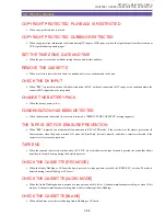
AV insertion for both DV input and analog input is only possible when there is no copy protection (CGMS = 00).
•
If a value other than “00” is detected for CGMS, then the camcorder changes to Stop mode.
Содержание ZR70 MC A
Страница 12: ...ZR70 MC A ZR65 MC A ZR60 A CHAPTER 1 GENERAL DESCRIPTION OF PRODUCT 1 9 External View Fig 1 1 ...
Страница 167: ...ZR70 MC A ZR65 MC A ZR60 A CHAPTER 4 DISASSEMBLING ADJUSTMENT 4 32 Rear Cover Unit Right Cover Unit Left Cover Unit ...
Страница 190: ...5 4 ZR70 MC A ZR65 MC A ZR60 A Front Cover Unit Section 4 1 2 6 7 8 3 2 5 3 3 ...
Страница 194: ...5 8 ZR70 MC A ZR65 MC A ZR60 A Left Cover Unit Section 2 7 3 2 2 2 2 8 2 5 7 6 9 1 3 4 A A ...
Страница 200: ...5 14 ZR70 MC A ZR65 MC A ZR60 A LCD Unit Section 1 3 2 1 3 4 5 10 2 6 7 9 8 ...
Страница 202: ...5 16 ZR70 MC A ZR65 MC A ZR60 A Rear Cover Unit Section 7 4 1 1 3 5 8 6 8 4 2 CVF Unit 1 3 ...
Страница 204: ...5 18 ZR70 MC A ZR65 MC A ZR60 A CVF Unit Section 1 2 6 7 8 9 10 11 12 17 17 2 18 19 13 14 15 16 3 5 4 2 4 2 A A ...
Страница 206: ...5 20 ZR70 MC A ZR65 MC A ZR60 A Recorder Unit Section CAMERA LENS UNIT 12 2 4 3 5 6 3 12 3 7 9 11 10 8 3 2 1 12 ...
Страница 210: ...5 24 ZR70 MC A ZR65 MC A ZR60 A Lens Unit Section 3 2 10 4 5 7 9 8 7 8 1 3 6 2 6 2 ...
Страница 212: ...5 26 DMC III Mechanical Chassis Section 1 1 3 9 5 7 8 6 4 2 3 3 ...
Страница 214: ...5 28 DMC III Mechanical Chassis Section 2 1 2 3 4 5 6 7 8 6 1 9 10 13 11 12 ...
Страница 216: ...5 30 DMC III Mechanical Chassis Section 3 2 2 2 2 2 3 3 8 9 2 10 11 12 13 4 6 7 5 1 ...
Страница 218: ...5 32 DMC III Mechanical Chassis Section 4 1 3 4 5 8 9 6 10 7 2 ...


