ZR70 MC A, ZR65 MC A, ZR60 A
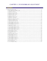
CHAPTER 4. DISASSEMBLING ADJUSTMENT
4-1
1. Disassembling and Reassembling
Notes :
(1) When replacing the flat cable with a new one, allow it to remain folded the same as the original part.
(2) The flat cable has a contact orientation to be engaged with the connector. Refer to the instructions in the disassembly procedure
diagram and interconnection diagram for boards.
⋅
Lateral engaging connector
(The instructions are given in the disassembly procedure diagram and board interconnection diagram.)
: Contacts are positioned downward. (board side)
∗
: Contacts are positioned upward.
⋅
Lengthwise engaging connector
(The instructions are given only in the boards interconnection diagram.)
Indicated by
→
. Arrowheads indicate the contacts, and the shafts indicate the noncontacts.
(3) To secure screws, apply the Three Bond 1401B (CY9-8011-000)
(4) If any part to be replaced has UL tape attached on it, be sure to reattach UL tape at the same position in reassembling.
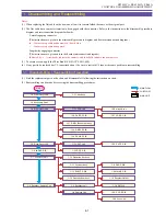
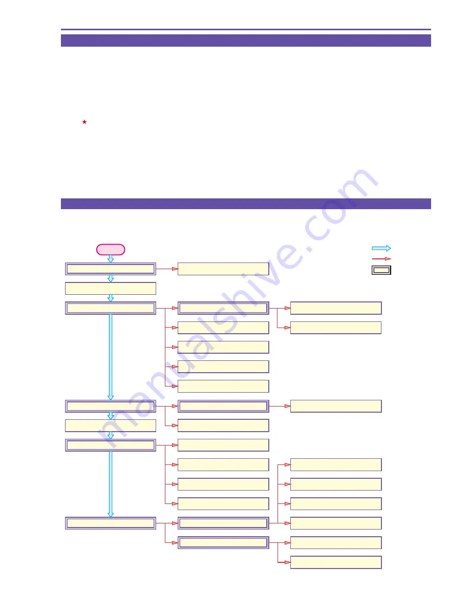
1-1 Disassembling / Reassembling Flowchart
(1) Find the replacement part on the chart, and disassemble it following the instruction on chart.
(2) Reassembling can be made by reversing the disassembling procedures.
START
: MAIN FLOW
: SUB FLOW
: MAIN UNIT
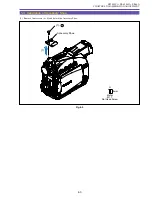
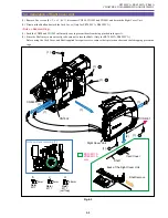
1-2 Front Cover Unit
1-11 Mic Ass'y
1-21 LCD P.C.B.
1-20 Hinge Ass'y
1-4 Right Cover Unit
1-15 LCD Unit
1-3 Accessory Shoe
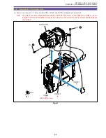
1-5 Rear Cover Unit
1-12 Operetion Key Ass'y
1-13 Speaker Ass'y
1-13 EJECT P.C.B.
1-14 Cassette Arm Ass'y
1-16 CARD P.C.B.
1-17 R-KEY Back Light Ass'y
1-18 R-KEY P.C.B.
1-18 DSW2 P.C.B.
1-23 DC P.C.B.
1-10 Recorder Holder
1-10 DMC III
1-9 CAC P.C.B.
1-9 MAIN P.C.B.
1-28 CCD P.C.B.
1-29 Lens Unit
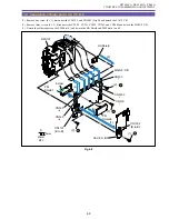
1-8 Recorder Unit
1-8 Camera Unit
1-6 JACK P.C.B.
1-8 Recorder, Camera Unit
1-7 Left Cover Unit
1-26 CVF P.C.B.
1-22 CVF Unit
Содержание ZR70 MC A
Страница 12: ...ZR70 MC A ZR65 MC A ZR60 A CHAPTER 1 GENERAL DESCRIPTION OF PRODUCT 1 9 External View Fig 1 1 ...
Страница 167: ...ZR70 MC A ZR65 MC A ZR60 A CHAPTER 4 DISASSEMBLING ADJUSTMENT 4 32 Rear Cover Unit Right Cover Unit Left Cover Unit ...
Страница 190: ...5 4 ZR70 MC A ZR65 MC A ZR60 A Front Cover Unit Section 4 1 2 6 7 8 3 2 5 3 3 ...
Страница 194: ...5 8 ZR70 MC A ZR65 MC A ZR60 A Left Cover Unit Section 2 7 3 2 2 2 2 8 2 5 7 6 9 1 3 4 A A ...
Страница 200: ...5 14 ZR70 MC A ZR65 MC A ZR60 A LCD Unit Section 1 3 2 1 3 4 5 10 2 6 7 9 8 ...
Страница 202: ...5 16 ZR70 MC A ZR65 MC A ZR60 A Rear Cover Unit Section 7 4 1 1 3 5 8 6 8 4 2 CVF Unit 1 3 ...
Страница 204: ...5 18 ZR70 MC A ZR65 MC A ZR60 A CVF Unit Section 1 2 6 7 8 9 10 11 12 17 17 2 18 19 13 14 15 16 3 5 4 2 4 2 A A ...
Страница 206: ...5 20 ZR70 MC A ZR65 MC A ZR60 A Recorder Unit Section CAMERA LENS UNIT 12 2 4 3 5 6 3 12 3 7 9 11 10 8 3 2 1 12 ...
Страница 210: ...5 24 ZR70 MC A ZR65 MC A ZR60 A Lens Unit Section 3 2 10 4 5 7 9 8 7 8 1 3 6 2 6 2 ...
Страница 212: ...5 26 DMC III Mechanical Chassis Section 1 1 3 9 5 7 8 6 4 2 3 3 ...
Страница 214: ...5 28 DMC III Mechanical Chassis Section 2 1 2 3 4 5 6 7 8 6 1 9 10 13 11 12 ...
Страница 216: ...5 30 DMC III Mechanical Chassis Section 3 2 2 2 2 2 3 3 8 9 2 10 11 12 13 4 6 7 5 1 ...
Страница 218: ...5 32 DMC III Mechanical Chassis Section 4 1 3 4 5 8 9 6 10 7 2 ...

