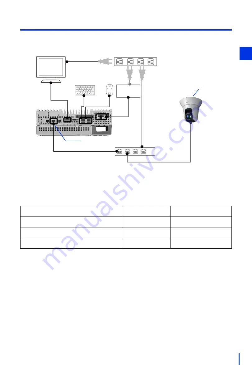
(1) Connect the Camera and the Image Processing Controller
23
In this example, the devices are connected as shown below.
DC 24 V
power supply
PoE Hub
IP address:
192.168.0.100
IP address:
192.168.0.2
The default IP addresses for network devices are shown below. The steps described in this
manual assume that no changes are made to these IP addresses.
Network Device
IP Address
Subnet Mask
Image processing controller (IPC427E)
192.168.0.100
255.255.255.0
Collaborative robot (COBOTTA)
192.168.0.1
255.255.255.0
Optional camera (N10-W02)
192.168.0.90
255.255.255.0
2
Содержание VB-H45
Страница 4: ...4 Camera Settings...
Страница 21: ...21 Device Connections...
Страница 27: ...27 Vision Edition Settings...
Страница 45: ...45 For Displayed Text enter Code Count Change Size to 36 Click OK 3 Click Add Value...
Страница 48: ...48 Operation Check...


