background image

3-20

CHAPTER 3.  REPAIR INSTRUCTION

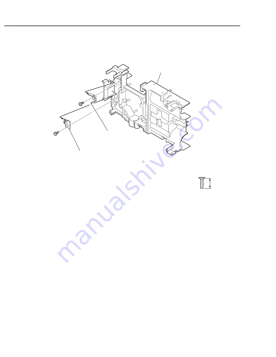
Fig. 3-20 LITHIUM (+) CONTACT, LITHIUM (-) CONTACT

2.18  LITHIUM (+) CONTACT, LITHIUM (-) CONTACT

(1) LITHIUM (+) CONTACT

1. Remove the screw 

c

.

2. Remove the LITHIUM (+) CONTACT in the direction of the arrow.

(2) LITHIUM (-) CONTACT

1. Remove the screw 

c

.

2. Remove the LITHIUM (-) CONTACT in the direction of the arrow.

METAL

M1.7

(SELF TAP)

XA4-9170-407

4.0mm

c

(2)-2 

LITHIUM (-) CONTACT

(1)-2 

LITHIUM (+) CONTACT

MAIN FRAME

(2)-1

(2)-2

(1)-2

c

(1)-1

c

Содержание PowerShot A300

Страница 1: ......

Страница 2: ...d Canon may issue new editions of this manual The following paragraph does not apply to any countries where such provisions are inconsistent with local law Trademarks The product names and company names described in this manual are the registered trademarks of the individual companies Copyright This manual is copyrighted with all rights reserved Under the copyright laws this manual may not be copi...

Страница 3: ... the reading should be between 1MΩ and 5 2MΩ When the exposed metal does not have a return path to the chassis the reading must be 4 2 Leakage Current Hot Check 1 Plug the AC cord directly into the AC outlet Do not use an isolation transformer for this check 2 Connect a 1 5KΩ 10 watt resistor paralleled by 0 15µF capacitor between each exposed metallic parts on the unit and a good earth ground suc...

Страница 4: ...gle of view 1 9 Three types of metering function 1 10 Total of 12 image quality modes 1 10 Settable display times for rec review 1 10 Direct Print function compatible 1 10 Sound memos of up to 60 seconds can be appended during replay 1 11 My Camera function 1 11 FAT12 FAT16 and FAT32 support 1 11 2 3 Fulfiled Movie Function 1 12 Three types of recording pixels for movie mode 1 12 Long movie record...

Страница 5: ...hotos 1 17 3 2 6 dimentional diagram 1 18 3 3 Nomenclature 1 19 3 4 UI Information 1 20 FUNC MENU 1 20 Rec MENU 1 21 My Camera MENU 1 21 Play MENU 1 22 Set up MENU 1 23 4 Specifications 4 1 Camera Specifications 1 24 4 2 Functions Availability and data s memory in each Shooting Mode 1 31 4 3 Replay compatibility 1 33 5 System 5 1 Accessories compatibility 1 34 5 2 System Diagram 1 36 ...

Страница 6: ...roduct Concept The concept behind the PowerShot A300 was to develop a high image quality high performance 3 megapixel class compact equipped with picture quality and performance rivaling high end models while staying at rock bottom prices The PowerShot A300 is still aimed toward first time digital camera buyers and users who want to enjoy a straightforward digital camera but it is also appealing t...

Страница 7: ...o 10 seconds Images can be erased during display Direct Print function compatible Card Photo Printers and Bubble Jet printers Sound memos of up to 60 seconds can be appended during replay My Camera function Customizeable of Start up image Start up sound Operation sound Self timer sound and Shutter sound on camera content can be also created FAT12 FAT16 and FAT32 support 5 Photo effect positions Vi...

Страница 8: ...ideways layout and stylish capsul shape CF card usable long time movie recording 256 MB Size AA NiMH rechargeable battery and charger AC adapter kit Win Windows Mac Macintosh Full feature application software ZoomBrowser EX Win ImageBrowser Mac enables customized image control and display Photorecord Win for easy layout and printing of many pictures PhotoStitch Win Mac for creating panoramic pictu...

Страница 9: ...is similar to that of the PowerShot A200 A100 the layout of the but tons functional markings and operability of each component have been fine tuned to make this an entry class digital camera that anyone can use easily The exterior has been given a more refined and distinguished look by changing to a sliding style lens cover ...

Страница 10: ...on On Flash On Flash Off Slow syncro 20 cm 2 0 m ISOequivalent speed AUTO O Auto Manual Stitch Assist Movie Approx 5 1 x Approx 4 0 x Vivid Neutral Low sharpening Sepia Black White O O Possible to set from 3 to 10 sec O O Approx 2 2 shots sec Large Fine LCD monitor off O Approx 2 0 shots sec Large Fine LCDmonitor off Operates with approx 2 or 10 sec count down Operates with approx 10 sec count dow...

Страница 11: ... English German French Dutch Danish Finnish Italian Norwegian Swedish Spanish Simplified Chinese and Japanese 11 languages English German French Dutch Danish Finnish Italian Norwegian Swedish Spanish and Japanese Start up image Start up sound Shutter sound Operation sound and Self timer sound Creation of on camera content USB Primary batteries Size AAAlkaline batteryx2 Secondary batteries Recharge...

Страница 12: ...gle sided lens Focusing is accomplished by a full sprocket method in which all five lenses move The 35 mm equivalent focal length of the lens has become slightly wider 33 mm compared with 39 mm for the Pow erShot A200 A100 due to the change in the screen size of the CCD sensor This allows the camera to get more out of composite photos and landscape shots For the same reason as the change in focal ...

Страница 13: ... cameras achieve precise exposure and white balance through an algo rithm optimized for the scene the user is about to shoot by analyzing the scene beforehand High precision white balance Auto Five preset positions Custom The PowerShot A300 adds custom white balance to the white balance functions auto and five position preset The custom white balance allows the user to record a desired white refer...

Страница 14: ...isplayed The cameras are also equipped with standard single center point AF enabling users to select the easiest AF function to suit the shooting con ditions Digital zoom function with continuously changing angle of view Approx 5 1x The digital zoom magnification of PowerShot A300 enlarges to approx 5 1x owing to employment of 3M pixel CCD It can adjust the field of view from 33mm to 168mm 35 mm f...

Страница 15: ... rec review Off can also be set Direct Print function compatible Card Photo Printers and Bubble Jet printers TheDirectPrintfunctionhasbeenequippedtothePowerShotA300so that high picture quality prints can be made easily by merely connecting the camera with the supplied cable to a Canon card photo printer CP 100 10 or Bubble Jet printers supporting the Direct Print function Refer to 5 2 System diagr...

Страница 16: ...On line photo service on the Canon Image Gateway 1 Web site accessible via ZoomBrowser EX ImageBrowser Also images or sounds 2 captured with the camera itself can be used as camera contents 1 Only for the Japanese market 2 The start up sound operation sound self timer sound and shutter sound can be recorded separately with the microphone FAT12 FAT16 and FAT32 support In the near future memoty card...

Страница 17: ...e speed of the CF card is slower 1 than the speed to write an image to the buffer the recording will stop when the buffer capacity is reached Taking this circumstance into account the specification limits the maximum recording time in VGA format to 30 sec When using FC 256MH and both QVGA and QQVGA formats to three minutes Even after 30 sec or 3 minutes of elapsed filming the PowerShot A300 allows...

Страница 18: ...end of the movie recording First frame Last frame Next frame Previous frame Fast forward and Rewind available during movie replay During movie replay on the PowerShot A300 next frame previous frame fast forward and rewind operations that correspond to those of a VCR are provided Instantaneous jumps to the start or end of a clip are also provided which are impossible with tape media Figure 2 10 Con...

Страница 19: ...ow to open and close the cover as well as making it possible to check if the cover is open or closed at a glance New UI Function buttons improves operability The PowerShot A300 include a Function button Pressing the Function button displays frequently accessed settings and likely values shooting parameters for each setting on the LCD monitor Desired settings can then be easily accessed with the cr...

Страница 20: ...rom the Communication setting on the camera menu the functions listed right can be controlled from the computer by simply connecting the cam era Twelve languages international support UI The menu screens displayed on the LCD monitor of the PowerShot A300 are available in 12 languages making these models suitable for use in the native or practical languages of most parts of the world The supported ...

Страница 21: ...f with a sliding lens cover appropriate for the upper model from the PowerShot A200 A100 Refer to Design Concept on page 4 2 6 System accessories CF card usable to long time movie recording FC 256MH A high capacity FC 256MH CF card with reduced write times has been configured to handle long time movie recording The capacity of the card is 256 MB ...

Страница 22: ...1 17 3 Exterior 3 1 Exterior Photos Photo 3 1 PowerShot A300 Front Photo 3 2 PowerShot A300 Rear ...

Страница 23: ...1 18 3 2 6 dimentional diagram 58 0 2 28 36 6 1 44 110 0 4 37 Unit mm inch ...

Страница 24: ...1 19 3 3 Nomenclature ...

Страница 25: ...oudy Custom Tungsten ISO Speed AUTO 50 100 200 400 Photo Effect Off Vivid Neutral Low Sharpening Sepia B W Compression Superfine Fine Normal Recording pixels Still Image Large 2048x1536 pixels Medium 1 1600x1200 pixels Medium 2 1024x768 pixels Small 640x480 pixels Movies 640 X 480 pixels 320 X 240 pixels 160 X 120 pixels ...

Страница 26: ...era MENU AiAF On Off Theme Start up Image Start up Sound Operation Sound Self Timer Sound Shutter Sound Selftimer 10 seconds 2 seconds AF assist Beam On Off Digital Zoom Review 3 to 10seconds 1 second increments On Off On ...

Страница 27: ...1 22 Play MENU Protect Transfer Order Rotate Sound Memo Erase all Auto Play Print Order ...

Страница 28: ...Set up MENU Beep Operation Vol Auto Power Down Selftimer Vol Date Time File No Reset Format Language Shutter Volume off to 5 Playback Vol off to 5 Start up Vol off to 5 On Off On Off On Off off to 5 off to 5 ...

Страница 29: ...LCD monitor Amorphous silicon TFT color LCD Approx 67 K pixels 38 mm diagonal 1 5 in 100 Not available Focusing TTL Autofocus Not available 5 point AiAF 1 point AF Fixed to center Normal Macro Landscape Not available Available Lens construction Aspect ratio Filter type Focal length f number Camera effective pixels Total pixels Transfer method Chip size Eyepoint Diopter adjustment Type Optical zoom...

Страница 30: ... Flash Built in Auto Red eye reduction auto On Off Slow syncro 20 cm 2 0 m 0 67 6 7 ft When ISOspeed is set to AUTO 1 60 1 500 sec 1 1 500 sec when in Slow syncro mode 10 sec or less battery voltage 3 15 V Not available Not available Available Available Not available Flash External Not available Metering methods Exposure control methods AE lock Exposure compensation Sensitivity Equivalent film spe...

Страница 31: ...ill available However the shooting speed is reduced Not available Operates with approx 2 sec or approx 10 sec count down Not available Shooting operation is possible with the use of RemoteCapture software when the camera is connected to PC Shooting modes Shooting functions Digital zoom Photo effects Image quality adjustment Noise reduction Bracketing Review Shooting interval Camera start up time R...

Страница 32: ...he CF card When the capacity of the CF card is 2GB or over FAT32 is selected Still image File format Image recording format JPEG compression mode Number of recording pixels Recording capacity Movie File format Recording format Number of recording pixels Frame rate Recording time Recording capacity Format Common Storage media Image Quality L SF L F L N M1 SF M1 F M1 N M2 SF M2 F M2 N S SF S F S N F...

Страница 33: ...e image data recorded with the Design rule for Camera File system s format can be erased However protected images cannot be erased Movie Part of movie All of movie Can be erased from start point to mid point or from mid point to end point with the movie editing function Furthermore can be erased both from start point to mid point and from mid point to end point Erase prohibited Set in replay mode ...

Страница 34: ...esting standard Normal temperature Repeat replayautomaticallyat a speed of 1 image per 3 seconds Factorydefault brightness setting Not available Approx 110 minutes Battery Charger CB 3AH Available Shooting mode Powers down approx 3 minutes after last operation Replaying mode Powers down approx 5 minutes after last operation Does not power down in Auto Play mode Printer connection Powers down appro...

Страница 35: ...amera specifications 0 40 10 90 110 0 x 58 0 x 36 6 mm 4 37 x 2 28 x 1 44 in Excluding protrusions Approx 175 g 6 17 oz Camera body only Dimensions W x H x D Weight Operating temperature Operating humidity C ...

Страница 36: ...1 31 ...

Страница 37: ...1 32 ...

Страница 38: ...1 33 ...

Страница 39: ...1 34 ...

Страница 40: ...1 35 ...

Страница 41: ...1 36 5 2 System Diagram ...

Страница 42: ...er Supply Block Diagram 2 2 2 1 2 Power Control Sequence 2 2 2 2 Signal Processing 2 3 2 2 1 System Control 2 3 2 2 2 Picture Processing 2 4 2 2 3 Audio Processing Recording and Playback Functions 2 4 3 Troubleshooting 3 1 When an Error Code is Displayed 2 5 3 2 When a Problem Occurs 2 7 CHAPTER 2 TECHNICAL DESCRIPTION CONTENTS ...

Страница 43: ...3 Controlling the power supply and the system by CPU Refer to Sections 2 1 and 2 2 4 Image processing and reading and writing the image signal to and from the CF card using DSP Refer to Section 2 2 2 5 LCD drive 6 Power supply drive DC DC converter 7 Backlight for LCD drive 1 2 FLASH UNIT 1 Flash drive and charging circuit for the flash Fig 1 FLASH UNIT RLS PCB ASS Y MAIN PCB ASS Y ...

Страница 44: ... CPU VBATT FUSE E1 OUTPUT E2 E21 OUTPUT E3 OUTPUT VBATT ORI for System Control for DSP for Image Process CCD etc for LCD E1 E2 E21 E3 MAIN PCB ASS Y VCC1M V VDD2 V VEE2 V VCC2 V VDD3 V for Motor Drive 3 0V REG REG V V VCC1 V VCC1A V VCC1L VCC1A_3 VCC1AL FUSE 3 3 2 5 1 5 7 5 3 3 3 3 15 3 3 12 2 1 2 Power Control Sequence Battery is Installed or DC IN Shooting Mode LCD OFF E2 LCD ON E2 E3 Playback M...

Страница 45: ...ignal processing and conversion of the digital data LCD Driver Driving the LCD FLASH MEMORY Firmware memory DSP Picture processing RTC Clock count for watch AF Support LED AF auxiliary self timer and red eye protection also serves as a lamp Electric Flash Flash and charging circuit CDS A D LCD Driver CCD Sensor LENS UNIT Motor Driver AF Support LED FINDER LED Electric FLASH CF card LCD TG RTC FLAS...

Страница 46: ...DSP 2 The DSP circuit performs the following signal processing Processes the picture data using the SDRAM Writes and reads the picture data to and from the CF card Outputs analog video signal to the LCD 3 The video signal that is supplied form the DSP is controlled by the LCD driver and is displayed on the LCD 2 2 3 Audio Processing Recording and Playback Functions 1 During recording of moving pic...

Страница 47: ...e of the image file until it can be successfully written to CF This error occurs when writing of the JPEG image file fails after 10 retries at increasingly higher compression ratios The power of the imaging circuit on the MAIN PCB ASS Y was not detected Detection of the focus PI photo interrupter failed Writing of the photograph image to SDRAM did not end within the specified time Cause and Probab...

Страница 48: ...mode The camera power was turned OFF while the image was being recorded to the CF Card The error code is displayed when the camera is next turned ON This error may occur after E23 The CF Card could not be formatted properly When image data cannot be read from CF normally Review of the photograph image failed Cause and Probable Faulty Part CF CARD MAIN PCB ASS Y The battery or DC plug was removed w...

Страница 49: ...VER UNIT FLASH UNIT BL FPC ASS Y MAIN PCB ASS Y BUTTON PCB ASS Y LCD PANEL BACK LIGHT UNIT OPTICAL UNIT MAIN PCB ASS Y MAIN PCB ASS Y BATTERY BOX UNIT REAR COVER UNIT FLASH UNIT MAIN PCB ASS Y MAIN PCB ASS Y CF CARD REAR COVER UNIT MAIN PCB ASS Y REAR COVER UNIT RLS PCB ASS Y Problem when an error code is not displayed The camera does not work The image is not displayed on the LCD Monitor The phot...

Страница 50: ...AL UNIT 1 3 17 2 16 OPTICAL UNIT 2 3 18 2 17 BATTERY LOCK PLATE BATTERY LOCKER 3 19 2 18 LITHIUM CONTACT LITHIUM CONTACT 3 20 2 19 Screw List 3 21 3 Adjustments 3 22 3 1 Replacement Parts and Adjustment Items 3 22 3 2 Adjustment Tools 3 23 3 3 Before Starting Electrical Adjustments 3 24 3 3 1 TWAIN Driver Installation 3 24 3 3 2 Factory Mode Driver Installation 3 24 3 3 3 Adjustment Software Insta...

Страница 51: ...cuit 1 2 List of Tools The following tools are used for the re assembling during service 1 List of tools New Name of tools Part No Areas where supplies are used Screwdriver commercially available on market Tweezers commercially available on market Soldering iron commercially available on market 1 3 List of Supplies The following supplies are used for the re assembling during service 1 List of supp...

Страница 52: ...s equipped with the holes as shown Use them for removal and insertion by inserting the tweezers into them as required 1 4 Flexible Connectors This product uses the two types of the flexible connectors Fig 3 3 Holes for removal Fig 3 2 Flexible connectors 1 LOCK UNLOCK Type A Type B UNLOCK LOCK Unconnected state The contact piece should face front The contact piece should face upwards connected sta...

Страница 53: ...has adhered to the parts should be removed CAUTION BATTERY COVER 3 6 REAR COVER UNIT 3 4 Be careful of high tension BACK LIGHT UNIT LCD PANEL 3 5 M S FPC 3 13 MICROPHONE MICROPHONE BUSH 3 8 BATTERY CONTACT BATTERY CONTACT 3 15 LITHIUM CONTACT LITHIUM CONTACT 3 20 MAIN PCB ASS Y MAIN SHIELD 1 CASE MAIN SHIELD 3 CASE 3 11 CCD UNIT CCD RUBBER IR FILTER OPTICAL UNIT 3 18 BATTERY LOCK PLATE BATTERY LOC...

Страница 54: ... of the arrow Remove connection of the LCD FPC and the MO FPC and remove the REAR COVER UNIT Remove the SIDE COVER at the same time NOTE1 Assembling During assembling check that the switch position is correct NOTE2 Assembling During assembling set the position of the REAR COVER UNIT NOTE1 Assembling NOTE2 Assembling CAUTION 1 1 BATTERY COVER SIDE COVER 1 3 REAR COVER UNIT LCD FPC MO FPC 1 4 1 2 1 ...

Страница 55: ...T 4 Disengage the four claws at the top bottom right and left The separate the BACK LIGHT UNIT LIGHT SHADING SHEET and LCD PANEL each other CAUTION Be careful that the LIGHT SHADING SHEET should not drop when separating them NOTE3 Assembling In the case of the service part the protection sheet is attached Remove the protection sheet before assembling NOTE1 Assembling NOTE2 Assembling NOTE3 Assembl...

Страница 56: ... the direction of the arrow 2 Insert tweezers or the like and disengage the two claws and two dowels and remove the BATTERY CONTACT PLATE in the direction of the arrow NOTE Assembling Align it with the two claws and two dowels NOTE Assembling 1 1 BATTERY COVER 1 1 1 2 1 1 Claws Dowels Tweezers 1 2 BATTERY CONTACT PLATE ...

Страница 57: ...h the terminal of capacitor When the FRONT COVER UNIT is removed be sure to discharge the capacitor 2 CF COVER BATTERY COVER SPRING 1 Remove the CF COVER 2 Remove the BATTERY COVER SPRING Fig 3 7 FRONT COVER UNIT CF COVER BATTERY COVER SPRING NOTE Assembling CAUTION ELECT CAPASITOR How to discharge the capacitor Never touch the terminals of the capacitor terminal Orange Gray terminal ELECT CAPASIT...

Страница 58: ...CROPHONE 1 NOTE Assembling Be careful of the direction of the two lead wires black and red After soldering apply the DIA BOND 1663G 2 Remove the MICROPHONE and MICROPHONE BUSH together as a single unit in the direction of the arrow 3 Separate the MICROPHONE from the MICROPHONE BUSH NOTE Assembling 1 1 Soldering 1 2 Red Red Black Black 1 2 1 3 MICROPHONE BUSH 1 3 MICROPHONE 1 2 MICROPHONE MICROPHON...

Страница 59: ...the CCD FPC 5 Remove connection of the OPT FPC 6 Remove the three screws c and remove the MAIN PCB ASS Y the MAIN SHIELD 1 CASE MAIN SHIELD 2 CASE and MAIN SHIELD CASE together as one unit in the direction of the arrow NOTE2 Assembling Align it with the two dowels that determine position of the MAIN FRAME METAL M1 7 SELF TAP XA4 9170 407 4 0mm c NOTE1 Assembling Setting the position during assembl...

Страница 60: ...e MAIN SHIELD 2 CASE NOTE Assembling Attach the insulation tape at the specified position Fig 3 10 MAIN PCB ASS Y 2 NOTE Assembling 1 1 Soldering 1 2 Insulation tape Insulation tape Position where insulation tape is to be attached 1 2 MAIN SHIELD 2 CASE MAIN SHIELD 2 CASE MAIN PCB ASS Y MAIN SHIELD 1 CASE MAIN SHIELD 3 CASE ...

Страница 61: ...sition 2 Remove the MAIN SHIELD 3 CASE 3 Remove soldering from the three positions 4 Separate the MAIN SHIELD 1 CASE from the MAIN PCB ASS Y NOTE Assembling Attach the insulation tape at the specified position 1 2 1 2 1 2 MAIN SHIELD 3 CASE 1 4 MAIN PCB ASS Y 1 4 MAIN SHIELD 1 CASE 1 4 1 4 1 4 NOTE Assembling 1 1 Soldering 1 1 Soldering 1 3 Soldering Insulation tape ...

Страница 62: ...n between the mold portion of the FLASH UNIT and the MAIN FRAME and remove the FLASH UNIT from the dowels 4 Remove the screws c Remove the GND PLATE at the same time 5 Remove the FLASH UNIT in the direction of the arrow NOTE3 Assembling Align it with the two dowels that set the positions METAL M1 7 SELF TAP XA4 9170 407 4 0mm c NOTE1 Assembling NOTE2 Assembling NOTE3 Assembling 1 4 1 1 1 1 Orange ...

Страница 63: ...3 13 CHAPTER 3 REPAIR INSTRUCTION Fig 3 13 M S FPC 2 11 M S FPC 1 M S FPC 1 Remove the M S FPC NOTE Assembling Fold the M S FPC into the three equal lengths as shown NOTE Assembling FLASH UNIT M S FPC ...

Страница 64: ...aw and the two dowels and remove the RLS PCB ASS Y in the direction of the arrow NOTE Assembling Align it with the claw and the two dowels Fig 3 14 RLS PCB ASS Y METAL M1 4 SELF TAP XA4 9140 257 2 5mm d 1 1 OPT FPC 1 3 RLS PCB ASS Y 1 2 1 1 Claw Dowel for setting the position Dowel for setting the position d NOTE Assembling NOTE Assembling ...

Страница 65: ... the way of pushing it from the rear of the MAIN FRAME 2 Remove soldering and remove the BATTERY LEAD NOTE2 Assembling After soldering apply the DIA BOND 1663G 3 Remove the BATTERY CONTACT GUARD NOTE3 Assembling Route the lead wire as shown in the illustration NOTE1 Assembling NOTE2 Assembling NOTE3 Assembling MAIN FRAME 1 1 BATTERY CONTACT 2 1 BATTERY CONTACT BATTERY CONTACT BATTERY CONTACT How t...

Страница 66: ...le sided adhesive tape to ELECT CAPACITOR 2 Remove soldering and remove the two lead wires gray and orange 1 NOTE2 Assembling Route the wires as shown in the illustration and apply the DIA BOND 1663G after soldering MAIN FRAME 1 1 ELECT CAPACITOR ELECT CAPACITOR 1 2 Soldering Orange Orange Double sided adhesive tape Gray Gray 1 1 DIA BOND 1663G DIA BOND 1663G NOTE1 Assembling NOTE2 Assembling How ...

Страница 67: ...L UNIT IR FILTER CCD RUBBER and CCD UNIT together as one unit in the direction of the arrow NOTE Assembling Align it with the two dowels that determine position of the MAIN FRAME METAL M1 7 SELF TAP XA4 9170 407 4 0mm c MAIN FRAME 1 2 OPTICAL UNIT IR FILTER CCD RUBBER CCD UNIT 1 2 Setting the position during assembling 1 1 c NOTE1 Assembling ...

Страница 68: ...IT NOTE1 Assembling Align it with the two dowels that determine position of the OPTICAL UNIT 3 Remove the CCD RUBBER 4 Remove the IR FILTER 1 NOTE2 Assembling Apply the DIA BOND 1663G METAL M1 4 SELF TAP XA4 9140 307 3 0mm e NOTE1 Assembling NOTE2 Assembling OPTICAL UNIT Setting the position during assembling CCD UNIT 1 1 1 2 CCD RUBBER 1 3 IR FILTER 1 4 e ...

Страница 69: ...LATE BATTERY LOCKER 1 BATTERY LOCK PLATE BATTERY LOCKER 1 Remove the screw c 2 Remove the BATTERY LOCK PLATE 3 Remove the BATTERY LOCKER NOTE Assembling Insert it into groove NOTE Assembling METAL M1 7 SELF TAP XA4 9170 407 4 0mm c 1 2 BATTERY LOCK PLATE MAIN FRAME 1 3 BATTERY LOCKER 1 1 Groove c ...

Страница 70: ...CT 1 LITHIUM CONTACT 1 Remove the screw c 2 Remove the LITHIUM CONTACT in the direction of the arrow 2 LITHIUM CONTACT 1 Remove the screw c 2 Remove the LITHIUM CONTACT in the direction of the arrow METAL M1 7 SELF TAP XA4 9170 407 4 0mm c 2 2 LITHIUM CONTACT 1 2 LITHIUM CONTACT MAIN FRAME 2 1 2 2 1 2 c 1 1 c ...

Страница 71: ...UCTION 2 19 Screw List METAL M1 7 SELF TAP XA4 9170 607 6 0mm b SILVER M1 7 SELF TAP CD3 0443 000 4 0mm a METAL M1 7 SELF TAP XA4 9170 407 4 0mm c METAL M1 4 SELF TAP XA4 9140 257 2 5mm d METAL M1 4 SELF TAP XA4 9140 307 3 0mm e ...

Страница 72: ...NIT FLASH UNIT MAIN PCB ASS Y LCD PANEL BACK LIGHT UNIT CCD Adjustment 1 1 Optical Unit Adjustment 2 2 Imaging Process Adjustment 3 Pixel Dot Adjustment 5 Flash Adjustment 6 Color Adjustment 4 Adjustment is necessary after replacement Adjustment is necessary after replacement Adjustment is not necessary only if the adjustment data has been saved and then transferred after the part is replaced Blan...

Страница 73: ...r Viewer 5600 K Color Bar Chart 18 Gray Chart Auto Focus Chart Zoom Chart W 10 Filter 1 C 12 Filter FL W Filter ND 2 Filter ND 4 Filter ND 8 Filter Light Shielding Cloth 500 500 or larger Tripod Reference Camera DIGITAL CAMERA SolutionDisk PARTS NO CY8 4385 031 DY9 2039 100 DY9 2002 000 CY4 6016 000 CY9 1556 000 CY9 1555 000 CY9 1557 000 CY9 1552 000 CY9 1553 000 CY9 1554 000 REMARKS Local purchas...

Страница 74: ...on After downloading and extracting Factory Mode Driver double click Setup exe Factory Mode Driver Win 2000_98 Setup exe to install it If InstallShield Wizard appears as shown in the first picture below install the TWAIN Factory Mode Driver by following the instructions 1 2 The InstallShield Wizard will install TWAIN Driver on your computer Click the N button License Agreement See the file Service...

Страница 75: ...ctory Mode Driver is completed NOTE If you cannot install Factory Mode Driver in above procedure install it in the following procedure 1 Change the camera to Factory mode 2 Install Wizard of new hardware starts up 3 Select the option that directly chooses the driver s place 4 Choose CAP_FACT INF Factory Mode Driver Win2000_98 Win_2k98 CAP_FACT INF 5 Installment starts When the Wizard finishes the ...

Страница 76: ...k box 3 When the dialog box below appears click the button Software installation will then begin 3 3 3 Adjustment Software Installation 1 After downloading and extracting Adjustment Software double click Setup exe to install it Adjustment Softwares are different according to the model of camera that you are going to adjust 2 When the dialog box below appears click the OK button ...

Страница 77: ...mpact Power Adapter CA PS800 and AC Cable 3 Set the Replay Mode on the camera and turn on 4 Set the Communication Mode to Normal 5 Connect the Camera s Digital terminal to the PC s USB Port with INTERFACE CABLE IFC 300 PCU 6 Turn on the camera Note Perform the preparation in the following order otherwise the camera won t work properly Personal Computer USB INTERFACE CABLE IFC 300PCU DIGITAL Compac...

Страница 78: ... PTP When calibration and adjustment are completed be sure to change the mode to the USER mode before quitting the software Calibration Adjustment For starting click the button related with calibration adjustment Whenever you use your light source for the adjustment for the first time be sure to click the Cali bration Button Quitting the Adjustment Software Click the Exit button Saving or Loading ...

Страница 79: ...WARE Color Viewer 5600 K ND 2 Filter Compact Power Adapter CA PS800 Color Bar Chart ND 4 Filter AC Cable W 10 Filter 2pcs ND 8 Filter INTERFACE CABLE IFC 300PCU C 12 Filter Reference Camera Merchandise 2 1 When the message on the right appears check that the reference camera Merchandise is con nected to the computer 2 Click the OK button 3 When the message on the right appears go to 4 ...

Страница 80: ...Filters between the Lens and the Color Viewer 2 Place the camera so that the lens is set against the center part of the Color Viewer 3 Click the ADJUST button Personal Computer Power Source Brightness Box CAMERA BODY C 12 Filter Power Source Stand Color Viewer Personal Computer CAMERA BODY ND 2 Filter 4 1 Place the camera so that lens is set against the light source surface of the Brightness Box v...

Страница 81: ... ND 2 Filter 2 Attach the two W 10 Filters between the Lens and the Color Viewer Place the camera so that the lens is set against the center part of the Color Viewer 3 Click the ADJUST button 10 When the message on the right appears go to 11 11 1 Remove the two W 10 Filters 2 Attach the C 12 and FL W Filter between the Lens and the Color Viewer Place the camera so that the lens is set against the ...

Страница 82: ...1 Attach the Color Bar Chart to the Color Viewer 2 Place the camera so that the Viewing image of the color bar chart is the full of LCD with the ND 4 Filter attached 3 Click the ADJUST button 14 1 Shift a frame on the displayed screen with a mouse to choose a color of color bar 2 Click the Sampling button 15 Check Save as the Reference and click the OK button to store the data ...

Страница 83: ...3 33 CHAPTER 3 REPAIR INSTRUCTION 16 When the message on the right appears click the FINISH button This ends the Calibration ...

Страница 84: ... ADJUSTMENT SOFTWARE Brightness Box light source A Compact Power Adapter CA PS800 C 12 Filter AC Cable 1 Click the CCD button 2 When the message on the right appears go to 3 3 1 Place the camera so that lens is set against the light source surface of the Brightness Box via the C 12 Filter 2 Set the Brightness Box to EV12 3 Click the ADJUST button When the adjustment does not work click the Default...

Страница 85: ... 4 When the message on the right appears Set the Brightness Box to EV15 while setting the C 12 Filter between the lens Click the ADJUST button 5 When the message on the right appears click the FINISH button This ends the CCD Adjustment ...

Страница 86: ...m Chart AC Cable Tripod 1 Click the Optical Unit button 2 When the message on the right appears go to 3 3 1 Place the Zoom Chart at 42 5cm away from the front of the camera finder Place the Zoom Chart on a plain color wall or equivalent Adjust the light so that the brightness of the chart will be about EV8 5 2 Adjust the position of the camera finely so that the center of the Auto Focus Chart is a...

Страница 87: ...3 37 CHAPTER 3 REPAIR INSTRUCTION 4 When the message on the right appears click the FINISH button This ends the Optical Unit Adjustment ...

Страница 88: ...SOFTWARE C 12 Filter Compact Power Adapter CA PS800 FL W Filter AC Cable ND 2 Filter INTERFACE CABLE IFC 300PCU Tripod Color Viewer 5600 K 1 Click the Imaging Process button 3 1 Attach the ND 2 Filters between the Lens and the Color Viewer 2 Place the camera so that the lens is set against the center part of the Color Viewer 3 Click the ADJUST button 2 When the message on the right appears go to 3...

Страница 89: ...essage on the right appears go to 5 6 When the message on the right appears go to 7 7 1 Remove the W 10 Filters 2 Attach the C 12 and FL W Filter between the Lens and the Color Viewer Place the camera so that the lens is set against the center part of the Color Viewer 3 Click the ADJUST button Power Source Stand Color Viewer Personal Computer CAMERA BODY W 10 Filter Power Source Stand Color Viewer...

Страница 90: ...3 40 CHAPTER 3 REPAIR INSTRUCTION 8 When the message on the right appears click the FINISH button This ends the Imaging Process Adjustment ...

Страница 91: ...r Bar Chart AC Cable ND 4 Filter 1 Click the Color button Color Viewer Color Bar Chart Personal Computer CAMERA BODY Power Source Stand ND 4 Filter 2 When the message on the right appears go to 3 3 1 Attach the Color Bar Chart to the Color Viewer 2 Place the camera so that the Viewing image of the color bar chart is the full of LCD with the ND 4 Filter attached 3 Click the ADJUST button ...

Страница 92: ...C moni tor satisfies the specifications 2 If the image on the PC monitor does not satisfy the specifications change the data using UP DOWN button or change the data directly by typing the data in the text box Then click the UPDATE button 4 1 Shift a frame on the displayed screen with a mouse to choose a color of color bar 2 Click the Sampling button 7 When the adjustment is completed click the FIN...

Страница 93: ...CA PS800 C 12 Filter AC Cable Light Shielding Cloth 500 500 or larger 1 Click the Pixel Dot button Personal Computer Power Source Brightness Box CAMERA BODY C 12 Filter 2 When the message on the right appears go to 3 3 1 Place the camera so that lens is set against the light source surface of the Brightness Box via the C 12 Filter 2 Set the Brightness Box to EV12 3 Click the ADJUST button ...

Страница 94: ... the message on the right appears cover the camera with the Light Shielding Cloth so that the no light reasons the CCD 2 Click the ADJUST button 5 When the message on the right appears click the FINISH button This ends the Pixel Dot Adjustment ...

Страница 95: ... SOFTWARE 18 Gray Chart Compact Power Adapter CA PS800 Tripod AC Cable 1 Click the Flash button 2 When the message on the right appears go to 3 3 1 Set 18 Gray Chart 60cm from the Finder front 2 Make the room as dark as a darkroom 3 Click the ADJUST button Personal Computer Power Source 18 Gray Chart 60cm CAMERA BODY Tripod ...

Страница 96: ...3 46 CHAPTER 3 REPAIR INSTRUCTION 4 When the message on the right appears click the FINISH button This ends the Flash Adjustment ...

Страница 97: ...7 CHAPTER 3 REPAIR INSTRUCTION 3 5 7 Checking of sound recording output It is not required to adjust the recording output volume etc of sound Check the camera if the sound is recorded play backed properly ...

Страница 98: ...2 Pg3 Accessories 1 Pg4 Accessories 2 Pg5 Service Tools 1 Pg6 Service Tools 2 Pg7 Category of CLASS A Frequency of use High B Frequency of use Middle C Frequency of use Low D Safety related critical parts E Consumable parts F Standard screws and washers S Supply of the parts is limited Y Service Tools ...

Страница 99: ...PowerShot A300 Casing Parts Pg1 1 2 3 4 5 6 7 8 9 12 10 11 13 14 15 15 14 14 N S ...

Страница 100: ...UMBER E 13361xxxxx CY1 6288 000 B 1 PLATE BODY NUMBER CH 13661xxxxx 4 CD3 0417 000 B 1 COVER CF 5 CD3 0413 000 C 1 PLATE BATTERY CONTACT 6 CD3 0412 000 B 1 COVER BATTERY 7 CD3 0410 000 B 1 COVER SIDE 8 CY1 6282 000 B 1 REAR COVER UNIT 9 CD3 0445 000 B 1 HOLDER LITHIUM BATTERY 10 CK9 1006 000 C 1 PANEL LCD CK9 1006 001 C 1 PANEL LCD SELECTION 11 CD3 0776 000 C 1 SHEET LIGHT SHIELDING 12 CM1 2006 00...

Страница 101: ...PowerShot A300 Pg2 Internal Parts 1 RED RED BLACK BLACK 1 2 3 4 5 6 7 8 9 10 11 12 13 14 15 16 17 18 21 21 19 20 22 ...

Страница 102: ...D3 0452 000 C 1 CONTACT BATTERY 9 CD3 0414 000 C 1 SPRING BATTERY COVER 10 CM1 2004 000 C 1 PCB ASS Y RLS 11 CD3 0420 000 C 1 CASE MAIN SHIELD 3 12 CD3 0419 000 C 1 CASE MAIN SHIELD 2 13 CM1 2001 000 C 1 PCB ASS Y MAIN 14 CD3 0418 000 C 1 CASE MAIN SHIELD 1 15 CD3 0441 000 C 1 BUSH MICROPHONE 16 WR1 5089 000 C 1 MICROPHONE 17 CK2 2016 000 C 1 LEAD MICROPHONE 18 CK2 2017 000 C 1 LEAD MICROPHONE 19 ...

Страница 103: ...PowerShot A300 Pg3 Internal Parts 2 GRAY ORANGE 1 2 3 4 5 6 7 8 9 10 11 12 13 14 14 14 14 ...

Страница 104: ...LTER IR 4 CY1 6283 000 B 1 OPTICAL UNIT 5 CK2 2009 000 C 1 LEAD CAPACITOR 6 CK2 2008 000 C 1 LEAD CAPACITOR 7 CK9 1009 000 C 1 CAPACITOR ELECT 80MF 330V 8 CD3 0402 000 C 1 FRAME MAIN 9 CD3 0415 000 B 1 LOCKER BATTERY 10 CD3 0416 000 C 1 PLATE BATTERY LOCK 11 CD3 0453 000 C 1 CONTACT LITHIUM 12 CD3 0454 000 C 1 CONTACT LITHIUM 13 XA4 9140 307 F 3 SCREW 14 XA4 9170 407 F 6 SCREW ...

Страница 105: ... Accessories 1 N S Wrist Strap WS 200 USB Interface Cable IFC 300PCU AC Cable Canon Digital Camera Solution Disk Alkaline Batteries X2 N S N S 1 3 2 CF CASE 4 CF Card FC 16M N Sl N S Stand for No Stock Product available ...

Страница 106: ...ASIA AUSTRALIA C84 1176 000 S 1 CD ROM SOLUTION DISK VER 12 0 E F S FOR USA CANADA C84 1178 000 S 1 CD ROM SOLUTION DISK VER 12 0 J E SC FOR JAPAN ASIA AUSTRALIA 3 WT3 5062 000 C 1 AC CABLE J FOR JAPAN WT3 5063 000 C 1 AC CABLE N FOR USA CANADA WT3 5064 000 C 1 AC CABLE E FOR EUROPE ASIA WT3 5115 000 C 1 AC CABLE B FOR USA WT3 5066 000 C 1 AC CABLE A FOR AUSTRALIA 4 FC2 9610 000 B 1 CASE CF Pg4 ...

Страница 107: ...PowerShot A300 Pg5 Accessories 2 Camera User Guide Software Starter Guide System Map 1 2 3 Quick Start Guide 4 ...

Страница 108: ...DE SPANISH FOR VER 12 0 FOR USA CDI J079 000 S 1 SOFTWARE GUIDE JAPANESE FOR VER 12 0 FOR JAPAN CDI F077 000 S 1 SOFTWARE GUIDE FRENCH FOR VER 12 0 FOR CANADA 3 CDI E079 000 S 1 SYSTEM MAP ENGLISH FOR USA CANADA ASIA AUSTRALIA CDI S069 000 S 1 SYSTEM MAP SPANISH FOR USA CDI J070 000 S 1 SYSTEM MAP JAPANESE FOR JAPAN CDI F068 000 S 1 SYSTEM MAP FRENCH FOR CANADA 4 CDI E080 000 S 1 QUICK START GUIDE...

Страница 109: ...erShot A300 Service Tools 1 Pg6 W 10 Filter 18 Gray Chart SERVICE MANUAL CD ROM C 12 Filter 5 ND 2 Filter 8 6 FL W Filter Color Viewer 5600 K Standard Color Bar Chart 7 3 2 ND 4 Filter 9 ND 8 Filter 10 4 1 ...

Страница 110: ...ROM SERVICE MANUAL J E 2 DY9 2039 100 Y 1 COLOR VIEWER 5600K 3 DY9 2002 000 Y 1 COLOR BAR CHART 4 CY4 6016 000 Y 1 CHART 18 GRAY 5 CY9 1555 000 Y 1 FILTER C 12 6 CY9 1556 000 Y 1 FILTER W 10 7 CY9 1557 000 Y 1 FILTER FL W 8 CY9 1552 000 Y 1 FILTER ND 2 9 CY9 1553 000 Y 1 FILTER ND 4 10 CY9 1554 000 Y 1 FILTER ND 8 Pg6 ...

Страница 111: ...PowerShot A300 Service Tools 2 Pg7 DIA BOND NO 1663G BLACK Adhesive Tape SONY T4000 Adhesive Tape 3M NO 56 1 2 3 Copper Foil Tape 3M 1181 4 ...

Страница 112: ... P A R T S L I S T PowerShot A300 1 CY9 8129 000 Y 1 BOND DIA BOND NO 1663G BLACK 2 CY4 6012 000 Y 1 ADHESIVE TAPE SONY T4000 6mm 50m roll 3 CY4 6018 000 Y 1 ADHESIVE TAPE 3M NO 56 15mm 66m roll 4 CY9 1559 000 Y 1 TAPE COPPER FOIL 3M 1181 1 2inch 18yard roll Pg7 ...

Страница 113: ...BLOCK DIAGRAMS 2 1 OVERALL 2 2 MAIN PCB ASS Y 1 4 2 3 MAIN PCB ASS Y 2 4 2 4 MAIN PCB ASS Y 3 4 2 5 MAIN PCB ASS Y 4 4 2 6 Abbreviation in Block Diagrams 3 P C B DIAGRAMS 3 1 MAIN PCB ASS Y 3 2 FLASH UNIT 3 3 OPR PCB ASS Y 3 4 RLS PCB ASS Y 3 5 BL FPC ASS Y ...

Страница 114: ... BLK RED BLK RED 1 1 5 6 2 20 1 1 1 24 24 1 6 1 1 28 6 20 1 3 CN101 DC IN BARRIER CLOSE SW BARRIER OPEN SW DETECT SWITCH CAPCITOR MIC CN104 FU102 FU101 WHT GRY GRY ORG BRN BLUE RED BATTERY DRY M S FPC BLK BLK FLASH LED BL FPC ASS Y MAIN PCB ASS Y FLASH UNIT CN1301 SW1 SW2 SW3 CN1902 CN1502 USB CN1001 CN1501 CN201 CN1002 CN1003 SPEAKER 1 9 CN302 CF Battery Cover Detect SW RLS PCB ASS Y ...

Страница 115: ...D 2 C_GND 3 VOUT 4 C_GND 5 C_GND 6 VDD VDD2 7 V1 8 RG 9 V2 10 V3A 11 SUB 12 V3B 13 CSUB 14 VL VEE2 15 V4 16 V5A 17 H1 18 H2 19 V5B 20 V6 CN1501 1 VCOM 2 VBC 3 G 4 B 5 R 6 VSH 7 VDD VCCIA 3 8 VSS 9 VGL 10 C2 11 C1 12 VSS 13 VDC VDD3 14 VGH 15 VDD VCCIA 3 16 HDI 17 DI 18 CLK 19 CS 20 XVD 21 PD 22 Not Connected 23 POCB 24 FRP 25 Not Connected 26 DSAVE 27 PSAVE 28 HDB CN1502 1 VBUS 2 D 3 D 4 Not Conne...

Страница 116: ...ver CDS A D T G SDRAM DC DC CONVERTER SW REG CONTROL for System Control for LCD for CCD FLASH MEMORY VCC1 FINDER LED AF Support SELF Red Eye LED VCC1M THERMISTER CPU USB Control USB MIC CN1502 KEY Switch VCC1L VBATT RESET RTC BATTERY Load Test AUDIO SP AMP OPTICAL UNIT MAIN PCB ASS Y REAR COVER UNIT 3 3 OPT FPC REAR COVER UNIT 2 3 BATTERY BOX UNIT DC_IN STILL MOVIE Switch Release Switch CF Open Sw...

Страница 117: ...02 X1002 27MHz TG MCK TG HD TG VD CLPOB2 TG RST VSUBCNT CCD2 CCD11 VXOUT CCDCLK SSGOUT0 SSGOUT1 SSGOUT5 P3 4 P3 0 Q1011 BUFFER 2SC4617R VDD2 VCC1AL AOUTP2 Q1010 BUFFER 2SC4617R AOUTP1 Q1012 BUFFER 2SC4617R P4L 2 SYNC R OUT 18 36 G Y VCC1 IC1501 LCD CONTROL CM7300F1 C1314 C1506 EX1 EX0 35 R R Y CR C1505 1 B B Y CB C1507 VDD3 EX13 25 24 SYNC IN VCC3 21 DI 22 CLK 23 CS SCLK3 SDATA3 LCD_CS CSYNC VCC1A...

Страница 118: ...EX55 IR1 EX55 IR2 OUT3 12 13 IN3 8 IN4 OUT4 10 EX62 SHCLS EX44 SHOP 8 7 9 10 5 2 EX56 AF1 EX57 AF2 3 4 5 6 3 SH SH 19 20 OPT FPC IRIS MOTOR SHUTTER MOTOR AF MOTOR TH101 THERMISTOR AF PI 14 AF RST COM 15 AF RST CO 7 5 6 EX58 AFENA1 EX47 AF RST Q1008 LED DRIVE DTC144EE P3 3 Q1009 LED DRIVE XP6213 1 2 4 1 2 4 IC1902 AND GATE TC7SET08FU EX63 STSPC VCC1A 3 VDD2 1 3 2 IC1901 1 2 COMPARATOR NJM12903R VCC...

Страница 119: ... CLK CKE PCDT 0 PCDT 15 SDWE SDDT 0 SDDT 31 SDADR 0 SDADR 11 SDBS 0 SDBS 1 SDDQM 0 SDDQM 3 SDCAS SDRAS SDCS 0 SDCLK SDCKE P1 0 P1 7 NPCRD PCADR 0 PCADR 2 8 3 16 11 CF D 0 15 CF A 0 10 CN1003 38 13 VCC1 22 21 2 23 4 3 6 5 48 47 27 49 29 28 31 30 19 20 17 18 15 16 12 14 10 11 34 8 D00 D15 A00 A10 IORD NPCWR 35 IOWR PCCE1 P3 6 7 CE1 PCCE2 32 CE2 PCRDY 42 WAIT PCIRQ 37 IREQ PCIOIS 24 IOIS16 P0 5 36 WE...

Страница 120: ...04 EFCHG 2 VCHGLVL 3 STSP 1 LED SELF 2 1 3 F 4 5 Q102 EF CHAGE 2SB1197K Q101 SWITCH DTC144EE Q103 OSC 2SC4672 T101 D104 D103 T102 FLASH AF SUPPORT LED SELF LED RED EYE LED From MAIN PCB ASS Y L2006 D2003 L2005 C2028 Q2005 PWM SW MCH3406 C2030 L2001 4 1 2 5 6 3 S D G Q2007 FET SI3445DV Q2009 SW DTC144EE C2017 T2001 C2019 L2002 L2003 C2024 8 1 2 7 5 6 3 4 D2004 L2009 IC2002 REG BD3987FV L2010 D2005 ...

Страница 121: ...ts 2 devices or circuits IGBT Insulated Gate Bipolar Transistor Conductivity modulation type FET transistor INV Logic Inverter circuit IR InfraRed ray IRIS Iris LCD Liquid Crystal Device Typically LCD display LED Light Emitting Diode Typically LED display LPF Low Pass Filter NTSC National Television System Committees NTSC color TV system developed in USA OP Amp OPerational Amplifier OR Logic OR ci...

Страница 122: ...C CANON INC 2003 01 April 2003 3 P C B DIAGRAMS 3 1 MAIN PCB ASS Y MAIN PCB ASS Y SOLDERING SIDE MAIN PCB ASS Y COMPONENT SIDE ...

Страница 123: ...C CANON INC 2003 01 April 2003 3 2 FLASH UNIT FLASH PCB ASS Y SOLDERING SIDE FLASH PCB ASS Y COMPONENT SIDE ...

Страница 124: ...C CANON INC 2003 01 April 2003 3 3 OPR PCB ASS Y ...

Страница 125: ...C CANON INC 2003 01 April 2003 3 4 RLS PCB ASS Y ...

Страница 126: ...C CANON INC 2003 01 April 2003 3 5 BL FPC ASS Y ...

Страница 127: ...int out the Auto Focus Chart Procedures 1 Click Print of the Menu Bar 2 Remove clicking from Shrink oversized pages to paper size and Expand small pages to paper size and then print on A4 or legal A3 can be used ...

Страница 128: ...PowerShot A300 Auto Focus Chart ...

Страница 129: ...PowerShot A300 Auto Focus Chart ...

Страница 130: ...AF Chart Dimensions Dimensions 83mm 62mm ...

Отзывы: