


2-2. Disassembly & Reassembly Procedures
(Click on the image to enlarge it.)
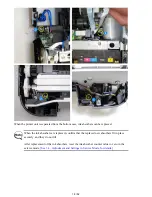
Be sure to protect the machine from static electricity in repair servicing, especially for the logic board, panel cover
unit, and PE sensor board.
Some of the photos below are from the MG5200 series, since their structure is similar to that of the iX6500 series.
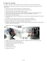
(1) External housing removal
iX6500 series
TABLE OF CONTENTS
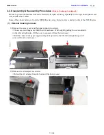
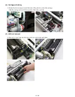
1) Remove the access cover and the paper support (no screws).
<The access cover hinges are fitted into the main case. While slightly pulling the cover outward
on the left and right sides, lift the cover to separate it from the main case.>
<Hold the center of the paper support, and pull it upward so that the left and right hinges will
come out from the main case.>
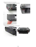
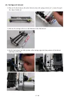
2) Remove the AC adapter (no screws).
<Pull out the AC adapter from the bottom of the bottom case.>
13 / 52
Содержание PIXMA iX6550
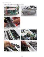
Страница 19: ...5 Remove the panel cover unit R 1 screw 15 52 ...
Страница 21: ...4 Remove the printer unit 6 screws Lift the printer unit Specific screw location 17 52 ...
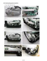
Страница 32: ... 10 Cable wiring and connection 1 Logic board and spur unit 28 52 ...
Страница 38: ... 2 Service Tool functions Service Tool screen Version 2 000 34 52 ...
Страница 39: ...35 52 ...
Страница 50: ...4 2 Integrated Inspection Pattern Print Print sample 46 52 ...
Страница 51: ...4 3 Ink Absorber Counter Value Print Print sample 4 VERIFICATION AFTER REPAIR 47 52 ...
Страница 54: ...50 52 ...