IV. INSTALLATION
A. Notes
Use the following power supplies;
• Line voltage (AC): ±10% of the rated voltage
• Power frequency: 50/60 Hz ± 2Hz
B. Unpacking and Installation
Condensation will form on the metal surfaces when brought into a warm room from the cold.
Therefore, when moving the unit into a warm environment, leave it packed in its box for at
least an hour to acclimatize to room temperature.
1. Opening the paper deck packaging
1) Undo the paper deck packaging, and remove the box.
2) Take out the accessories. Confirm that the power cord, outrigger kit, interface cables and
manual are included.
3) Remove the top pads (left/right) and remove the paper deck from the box.
4) Take the plastic bag off from around the deck and peel off the tape holding the various
parts. Check that none of the covers were scratched or deformed during shipment.
5) Open the tray, remove the 2 spacers, and peel off the tape.
6) Peel off the tape holding the latch of the paper guide.
2. Connecting to the printer
1) Carry the paper deck to the installation location and lock the casters.
2) Rotate the adjusters to install on the floor.
3) Open the feed unit.
4) Line up the printer and paper deck in the same direction, and have 4 people lift the printer.
Lower the printer onto the paper deck while aligning the 3 positioning pins on the paper
deck with the printer.
5) Close the feed unit.
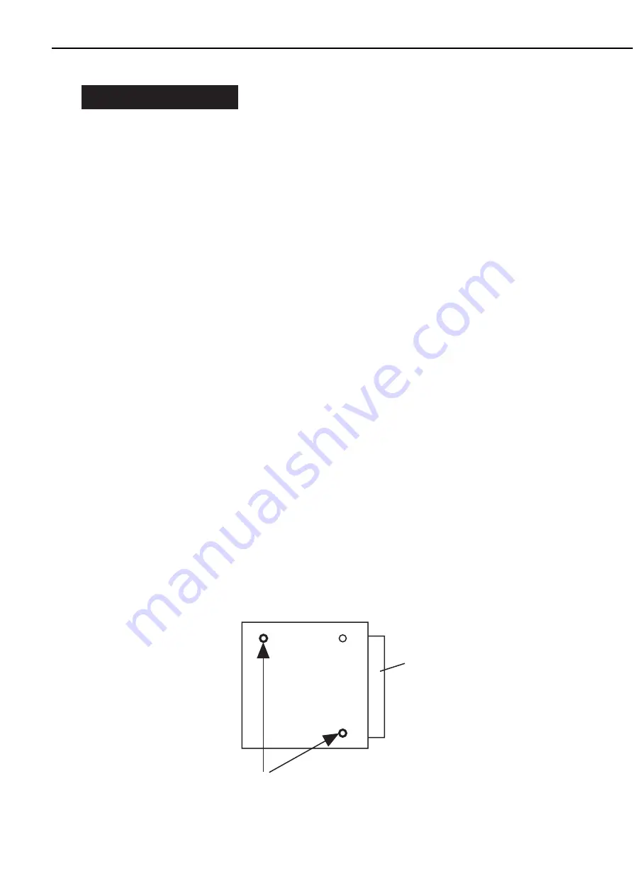
6) Remove the cassette from the printer. Put the snap pins (for earthquake countermeasure)
to the positioning pins.
7) Install the outriggers to the 2 guides at the bottom of the paper deck.
8) Put the covers to the 5 outriggers.
9) Connect the printer and paper deck with the interface cable.
10) Plug the power cord into the paper deck and the outlet.
Figure 1-4-1
1 - 5
CHAPTER 1
Feed unit
snap pin
• Snap pin insertion location
Содержание PD-82
Страница 8: ......
Страница 14: ......
Страница 16: ......
Страница 28: ......
Страница 30: ......
Страница 34: ...5 Rear cover 1 Remove the 4 screws and then the rear cover Screws Rear cover Figure 3 2 6 3 4 CHAPTER 3 ...
Страница 37: ...IV MAIN PARTS A Locations Lifter Figure 3 4 1 3 7 CHAPTER 3 ...
Страница 48: ...VII SOLENOID CLUTCH A Locations Pick up solenoid Registration clutch Figure 3 7 1 3 18 CHAPTER 3 ...
Страница 50: ...VIII MOTORS A Locations Lifter motor Pick up motor Feed motor Figure 3 8 1 3 20 CHAPTER 3 ...
Страница 58: ......
Страница 62: ...Figure 4 1 2 1 Pick up roller 2 Feed roller 3 Separation roller 4 4 CHAPTER 4 ...
Страница 80: ......
Страница 81: ...APPENDIX I GENERAL CIRCUIT DIAGRAM A 1 II LIST OF SIGNALS A 3 ...
Страница 82: ......
Страница 84: ......
Страница 88: ...PRINTED IN JAPAN IMPRIME AU JAPON 0199AB0 70 CANON INC The printing paper contains 70 waste paper ...


