


Chapter 5
5-2
F-5-5
5.2.2 Adjustment of Electrical Components
5.2.2.1 After Replacing the DC controller PCB
0015-8260
LBP5100
In the case that the DC controller PCB has been replaced, start the status win-
dow and execute the following procedure.
1) Execute Option Menu > Service Mode > Printer Information Settings >
Printer Setting Restoration.
After executing the printer recovery setting, wait completion of the process-
ing for approx. 15 sec.
2) Turn off/on the power supply of the host machine.
3) Execute Option Menu > Utility > Calibration.
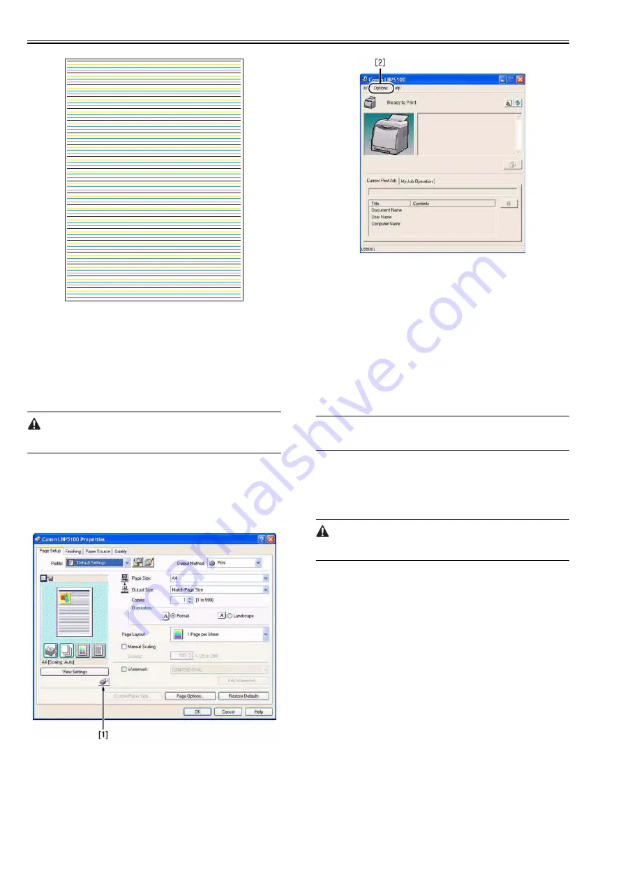
Step for Moving to Service Mode
1) After power on, display the printer driver screen.
2) Display the status window [1] from the driver screen.
3) Enter the password (*28*) with the numeric pad.
4) The service mode [2] is displayed on 'Option' menu of the status window
screen.
F-5-6
F-5-7
5.2.2.2 After Replacing the Video Controller PCB
0015-8261
LBP5100
In the case that the video controller PCB has been replaced, remove EEP-
ROM (ICS11S) from the old PCB and mount it in the new PCB.
Execute the following procedure when replacing the video controller PCB.
1) Turn on the power supply of the host machine.
2) Execute Option Menu > Utility > Calibration in the status window.
5.2.2.3 Replacing EEPROM (When E747-000 occurs)
0015-8262
LBP5100
1) Replace the video controller board or EEPROM (IC2S).
2) Turn on the power supply of the host machine.
3) Execute Option Menu > Utility > Calibration in the status window.
Memo
When EEPROM was replaced, a new USB serial number in EEPROM is as-
signed. The number of the printers on PC increases when USB is connected.
5.2.3 Adjustment of Fixing System
5.2.3.1 Checking the Nip Width (fixing pressure roller)
0010-6237
LBP5000 / LBP5100
Before removing the print paper, be sure to turn on the machine and see that
the machine is in a jam state. Otherwise, the fixing film can suffer a tear.
The machine can start to show poor fixing when the nip of its fixing assem-
bly is not correct. Check the nip of the fixing assembly first if poor fixing is
noted. You will not be able to adjust the nip. If the nip is wrong, replace the
assembly.
How to Check the Nip
1) Make a solid black print on A4/LTR paper, and take it to the user's.
2) Place the print in the machine's cassette with its printed side facing down.
3) Press the test print switch.
4) As soon as the leading edge of the print has appeared from the delivery
slot, turn off the power, and wait for about 10 sec, leaving the machine
alone.
5) Turn on the machine, and check to see that the machine is in a jam state.
Thereafter, remove the print with care.
6) On the print, measure the width of the area with shiny toner to see if it is
as indicated:
- middle (a): 6 +/-0.5 mm
- difference between left/right and middle (b - a, c - a): 0mm to 1mm
- difference between left and right (|b - c|): 0.8 mm or less
Содержание LBP5000 Series
Страница 1: ...Feb 26 2007 Service Manual LBP5000 5100 Series...
Страница 2: ......
Страница 6: ......
Страница 14: ...Contents...
Страница 15: ...Chapter 1 PRODUCT DESCRIPTION...
Страница 16: ......
Страница 18: ......
Страница 28: ......
Страница 29: ...Chapter 2 TECHNICAL REFERENCE...
Страница 30: ......
Страница 33: ...Contents 2 8 3 2 Overview of the Block 2 39...
Страница 34: ......
Страница 74: ...Chapter 2 2 40 IC12 Logic IC Converts voltage levels Notation Name Description...
Страница 75: ...Chapter 3 DISASSEMBLY AND ASSEMBLY...
Страница 76: ......
Страница 80: ......
Страница 122: ......
Страница 123: ...Chapter 4 MAINTENANCE AND INSPECTION...
Страница 124: ......
Страница 126: ......
Страница 132: ......
Страница 133: ...Chapter 5 TROUBLESHOOTING...
Страница 134: ......
Страница 136: ......
Страница 141: ...Chapter 5 5 5 F 5 9...
Страница 142: ...Chapter 5 5 6 F 5 10...
Страница 149: ...Chapter 6 APPENDIX...
Страница 150: ......
Страница 152: ......
Страница 161: ...Feb 26 2007...
Страница 162: ......


