background image

Fixing System

 Outline

The fixing/delivery unit fixes the toner onto a print paper and delivers it to the delivery tray.
The operation of the fixing/delivery unit is explained in the following.

1. The print paper fed from the pick-up/feed unit is fused the toner by the fixing film and the pressure roller.
2. The print paper delivered from the fixing unit is delivered to the face-down delivery tray or the face-up delivery slot. When

the engine controller detects that the heater temperature reaches 50 deg C after the last rotation is completed, it drives the
main motor for 50 msec. and dislocates the nip part. This prevents the toner adhering to the pressure roller.
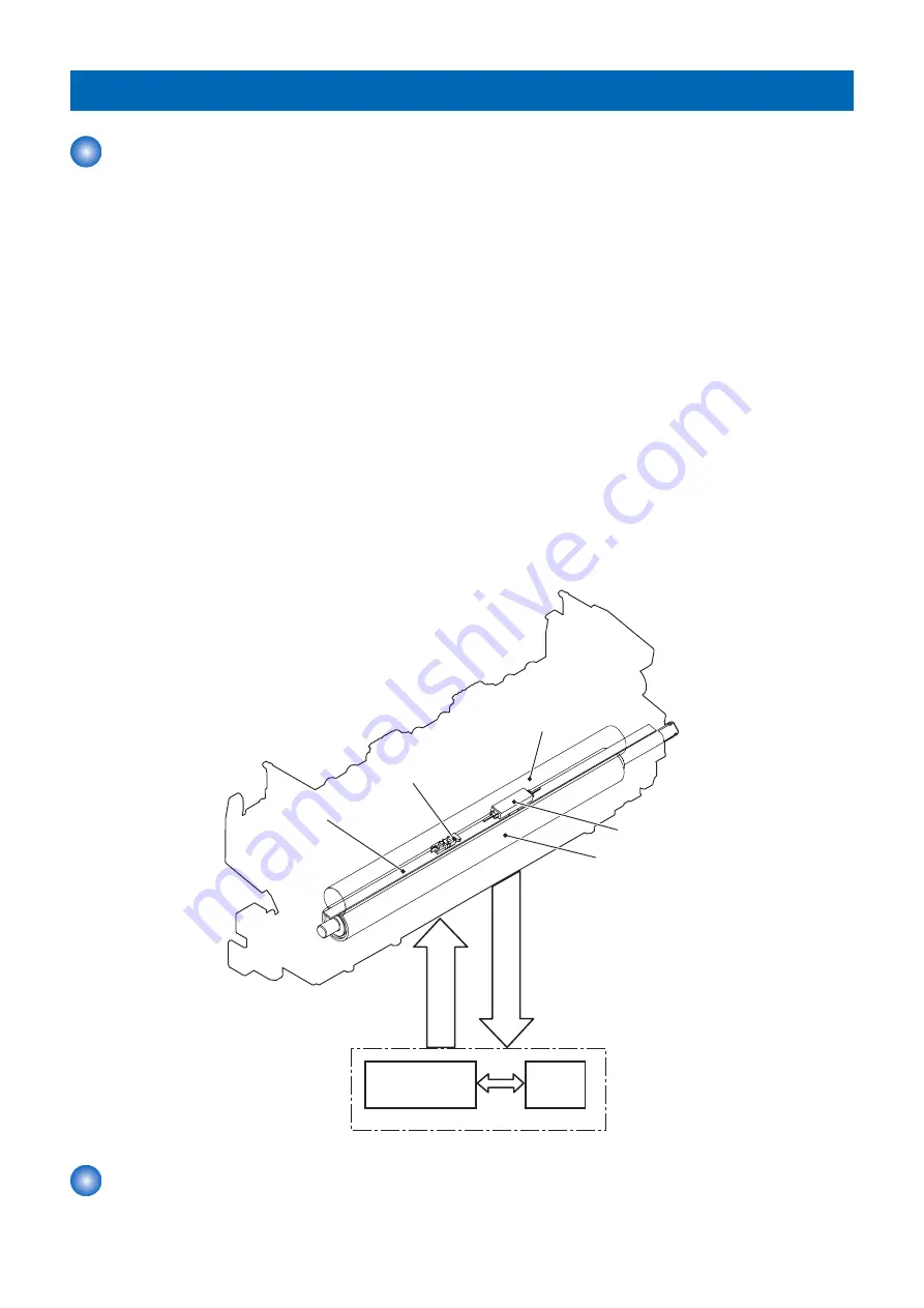
The fixing unit of this printer utilizes the on-demand fixing method. It is structured as shown below.

• Heater:

This fixing unit incorporates one heater.
Fixing heater (H1): To heat the fixing film (ceramic heater)

• Thermistor:

This fixing unit incorporates one thermistor.
Thermistor (TH1): Sit almost at the center of the fixing film. (contact type)
To control the temperature of the fixing film

• Thermal switch:

Thermoswitch (TP1): Sit almost at the center of the fixing film (contact type)
If the temperature of the heater rises abnormally high, the contact gets broken and cuts off the AC voltage supply to the
fixing heater to interrupt the power supply to the heater.

The temperature control of the fixing unit incorporated as above is operated by the fixing temperature control circuit according to
the command from the CPU (IC201) on the DC controller.
The followings describe the each circuit and function of the temperature control of the fixing unit.

Fixing film

Fixing unit

Thermistor

Fixing heater

Thermoswitch

Pressure roller

F

IXI

N

G

 T

EMPER

A

T

U

R

E

D

ET

EC

T

IO

N

 si

g

n

a

l

Engine controller PCB

CPU

F

IXN

G

 H

EAT

ER

 C

O

N

T

R

O

L

 si

g

n

a

l

Fixing heater

control circuit

 Fixing control circuit

The fixing control circuit controls the temperature in the fixing unit. The printer uses an on-demand fixing method.

2. Technology

22

Содержание LBP253 SM

Страница 1: ...Revision 1 0 LBP253 SM ...

Страница 2: ...a long or short period Canon will issue a new edition of this manual The following paragraph does not apply to any countries where such provisions are inconsistent with local law Trademarks The product names and company names used in this manual are the registered trademarks of the individual companies Copyright This manual is copyrighted with all rights reserved Under the copyright laws this manu...

Страница 3: ... door and closing the delivery unit door which results in supplying the machine with power 2 In the digital circuits 1 is used to indicate that the voltage level of a given signal is High while 0 is used to indicate Low The voltage value however differs from circuit to circuit In addition the asterisk as in DRMD indicates that the DRMD signal goes on when 0 In practically all cases the internal me...

Страница 4: ...rts 10 External View 10 Cross Sectional View 11 Operation 12 Operation Panel 12 2 Technology 13 Basic Operation 14 Function Structure 14 Sequence of Operation 15 Outline 15 Laser Exposure System 16 Outline 16 Optical Unit Failure Detection 16 Image Formation System 17 Outline 17 Image Formation Process 17 High voltage Power Supply 20 Fixing System 22 Outline 22 Fixing control circuit 22 Pickup Fee...

Страница 5: ... 69 External View 69 List of Main Unit 70 Motor Fan 72 Solenoid 72 Heater Thermo Switch Thermistor Switch 73 Sensor 74 PCB 75 Connector Layout Drawing 76 Connector List 76 External Cover Internal Cover 80 Removing the Left Cover 80 Removing the Right Cover 80 Removing the Rear Cover Unit Duplex Feed Unit 81 Removing the Upper Cover Unit 82 Removing the Cartridge Cover Unit 82 Controller System 84 ...

Страница 6: ...e Cassette Pickup Roller 100 Removing the Cassette Separation Pad 100 Removing the Multi purpose Pickup Roller 101 Removing the Multi purpose Separation Pad 101 5 Troubleshooting 103 Trouble Shooting 104 Test Pages 104 Confirming nip width 106 Version Upgrade 108 Overview 108 Version Upgrade Using UST 108 Upgrading via Internet 112 Corrective Actions 114 Image Defects 114 Debug Log 120 Function Ov...

Страница 7: ...APPENDICES 154 Service Tools 155 Special Tools 155 Solvents and Oil List 155 General Circuit Diagram 156 Print Sequence 157 Backup Data 158 Soft Counter Specifications 160 Contents iv ...

Страница 8: ...Safety Precautions Laser Safety 2 Toner Safety 2 Notes When Handling a Lithium Battery 3 Notes on Assembly Disassembly 3 ...

Страница 9: ...ing warnings are given to comply with Safety Principles EN60950 1 Diese Maschine ist der Klasse 1 der Laserprodukte zugeordnet Innerhalb der Scannereinheit befindet sich jedoch die Laserstrahlquelle der Klasse 3B und es ist gefährlich wenn dieser Strahl in die Augen gerät Die Laserscannereinheit darf unter keinen Umständen entfernt werden Es dürfen in diesem Umfeld der Maschine keine Justagen an d...

Страница 10: ...ssemble disassemble the device 1 Disconnect the power plug to avoid any potential dangers during assembling disassembling works 2 If not specially instructed reverse the order of disassembly to reinstall 3 Ensure to use the right screw type length diameter etc at the right position when assembling 4 To keep electric conduction binding screws with washers are used to attach the grounding wire and t...

Страница 11: ...Product Overview 1 Product Lineups 5 Features 6 Product Specifications 7 List of Parts 10 Operation 12 ...

Страница 12: ...ppearance Copy No Print Yes FAX No Remote UI Yes Automatic 2 sided Print 60 to 120g m2 paper Yes MEAP No Network Yes WLAN Yes Options No Name Description Remarks 1 Paper FeederUnit PF 44 Approx 500 Sheets Plain paper 80g m2 1 Product Overview 5 ...

Страница 13: ...nting In addition to the standard equipped universal cassette holds up to 250 sheets of 80g m2 paper and Multi purpose tray holds up to 50 sheets of 80g m2 paper the printer supports optional paper feeder holds up to 500 sheets of 80g m2 paper for a total capacity of 800 sheets Thus high volume continuous printing is available 4 LUI display LUI display touch panel display The display is a touch pa...

Страница 14: ...ette Paper Size Standard sizes A4 B5 A5 A6 Legal Letter Executive Custom size range user specified Width 105 0 to 215 9 mm Length 148 0 to 355 6 mm Multi Purpose Paper Size Standard sizes A4 B5 A5 A6 Legal Letter Executive Postcard Reply paid Postcard Four side Postcard Japanese Western style Envelope Size No 3 Envelope Size No 3 Custom size range user specified Width 76 2 to 215 9 mm Length 127 0...

Страница 15: ...z Maximum 990 W or less During operation Approx 570 W During standby Approx 11 7 W During sleep mode Approx 0 8 W USB connection Approx 1 0 W wired LAN connection Approx 1 6 W wireless LAN connection When the power switch is turned OFF 0 1 W or less Dimensions 403 W 376 D 320 H mm Weight Printer main unit approx 11 5 kg excl toner cartridges Option Paper Feeder Wireless LAN Item Specification func...

Страница 16: ...ding 2 Set the paper size switch lever in the same position as that for Letter Legal size 3 Custom size paper with width 105 0 to 216 0 mm and length 148 0 to 356 0 mm can be loaded 4 Custom size paper with width 76 2 to 216 0 mm and length 127 0 to 356 0 mm can be loaded Paper Type and Paper Source Capacity Chlorine free paper can be used with this machine Paper Type Paper Capacity for Paper Draw...

Страница 17: ...r 2 Multi purpose Tray 12 Face up Output Tray 3 Front Cover 13 Pressure Release Cover 4 Open Button 14 Left Cover 5 Upper Cover 15 USB Host 6 Control Panel 16 USB Device 7 Right Cover 17 LAN Connector 8 Power Switch 18 Duplex Unit Cover 9 Face down Output Tray Cover 19 Power Socket 10 Paper Cassette 1 Product Overview 10 ...

Страница 18: ...12 Multi purpose Tray Separation Pad 3 Pressure Roller 13 Registration Roller 4 Fixing Film Unit 14 Feed Roller 5 Fixing Unit 15 Cassette Pickup Roller 6 Transfer Roller 16 Cassette Separation Pad 7 Photosensitive Drum 17 Cassette 8 Laser Scanner Unit 18 Duplex Re pickup Roller 9 Cartridge 19 Duplex Feed Unit 10 Registration Shutter 20 Duplex Feed Roller 1 Product Overview 11 ...

Страница 19: ...ey 3 Reset key 12 Counter Check key 4 Back key 13 Stop key 5 Numeric keys 0 9 keys 14 key 6 key 15 Processing Data indicator 7 NFC Near Field Communication mark 16 Wi Fi indicator 8 Energy Saver key 17 Error indicator 9 Status Monitor key 18 Main Power indicator 1 Product Overview 12 ...

Страница 20: ...c Operation 14 Sequence of Operation 15 Laser Exposure System 16 Image Formation System 17 Fixing System 22 Pickup Feeding System 26 Controller System 29 Embedded RDS 34 Setting Information Export Import Function DCM 44 ...

Страница 21: ...cture of the printer contains the following five systems Engine control system Laser scanner system Image formation system Media feed system Option MEDIA FEED SYSTEM LASER SCANNER SYSTEM ENGINE CONTROL SYSTEM IMAGE FORMATION SYSTEM OPTION 2 Technology 14 ...

Страница 22: ... Maintains the printer in printable condition INTR Initial rotation From the time print command is received from the main controller unit the temperature of the fixing unit reaches its targeted tem perature Starts up each high voltage biases laser scanner and fixing unit in preparing for print operation PRINT From the end of INTR period unit the last media completes the fixing operation Forme the ...

Страница 23: ...rum BD sensor Laser unit LASER CONTROL signal VIDEO signal SCANNER MOT OR SPEED CONTROL signal BD INPUT signal Optical Unit Failure Detection The optical unit failure detection manages the laser scanner failure detection functions The DC controller determines an optical unit failure and notifies E100 to the Main controller if the laser scanner encounters the following conditions If the scanner mot...

Страница 24: ...am of the image formation system is shown below High voltage power supply DC controller Laser scanner Photosensitive drum Cartridge Transfer roller Laser beam Pressure roller Fixing film Fixing unit Engine controller Image Formation Process Outline The image formation process consists of the following seven steps divided among five functional blocks Latent image formation block Step 1 Primary char...

Страница 25: ...he drum directly Primary charging bias Photosensitive drum Primary charging roller Step 2 Laser beam exposure The laser beam scans the photosensitive drum to neutralize the negative charge on portions of the drum surface An electrostatic latent image forms where the negative charge was neutralized Laser beam Unexposed area Exposed area Developing block Toner adheres to the electrostatic latent ima...

Страница 26: ...ositively charged media attracts the negatively charged toner from the photosensitive drum surface Transfer bias Media Transfer roller Photosensitive drum Step 5 Separation The elasticity of the print media and the curvature of the photosensitive drum cause the media to separate from the drum surface The static charge eliminator reduces back side static discharge of the media for stable media feed...

Страница 27: ...scrapes the residual toner off the surface of the photosensitive drum The residual toner is deposited in the toner collection box Toner collection box Photosensitive drum Cleaning blade High voltage Power Supply Outline The high voltage power supply applies biases to the following components Primary charging roller Developing roller Transfer roller Fixing film The DC controller controls the high v...

Страница 28: ...y charging bias circuit Developing bias circuit Transfer bias circuit DC controller Engine controller Primary charging roller Cartridge Photosensitive drum Transfer roller Developing roller Fixing unit Pressure roller Fixing film 2 Technology 21 ...

Страница 29: ...mistor This fixing unit incorporates one thermistor Thermistor TH1 Sit almost at the center of the fixing film contact type To control the temperature of the fixing film Thermal switch Thermoswitch TP1 Sit almost at the center of the fixing film contact type If the temperature of the heater rises abnormally high the contact gets broken and cuts off the AC voltage supply to the fixing heater to int...

Страница 30: ...he fixing film Thermistor TH1 Detects fixing temperature Contact type Thermoswitch TP1 Prevents an abnormal temperature rise of the fixing heater Contact type These temperature controls in the fixing unit are performed by the fixing heater control circuit and the fixing heater safety circuit according to the commands from the DC controller Fixing temperature control The fixing temperature control ...

Страница 31: ...o the fixing heater The following three protective components prevent an abnormal temperature rise of the fixing heater DC controller Fixing heater safety circuit Thermoswitch 1 Thermoswitch The contact of the thermoswitch is broken to interrupt power supply to the fixing heater under the following condition Temperature fuse 228 C 442 4 F or higher 2 DC controller The DC controller monitors the de...

Страница 32: ...grees or lower for a specified period under the heater temperature control during the print period If the detected temperature of the thermistor does not reach its targeted temperature within a specified period under the heater temperature control during the initial rotation period 2 Abnormal high temperature E001 If the detected temperature of the main thermistor is kept a specified degrees or hi...

Страница 33: ...ixing film Fixing delivery roller Duplex feed roller Transfer roller Registration roller Duplex re pickup roller Cassette pickup roller MP tray separattion pad MP tray separattion roller Cassette separation pad Diagram and table of the electrical components are shown below Electrical component Signal Main Motor M1 Main Motor Control Signal Cassette Pickup Solenoid SL1 Cassette Pickup Solenoid Cont...

Страница 34: ...correctly or has jammed TOP sensor PS912 Fixing delivery sensor PS916 Duplex reverse sensor PS917 Media width sensor PS922 Simplex media path Duplex media path PS916 PS917 PS922 PS912 Pickup Delay Jam When the TOP Sensor PS912 cannot detect the leading edge of paper within the specified time after starting pickup from a cassette pickup retry is executed twice After that the sensor still cannot det...

Страница 35: ...oes not detect no paper within the specified time since the TOP Sensor PS912 detected the trailing edge of paper it is judged as a delivery stationary jam Reverse Delay Jam After judging that it is not a delivery stationary jam execute the detection of reverse stationary jam When the Duplex Reverse Sensor PS917 does not detect paper after the specified time has passed since the Fixing Delivery Sen...

Страница 36: ...upply Block diagram of the controller system is shown below Engine controller DC controller Low voltage power supply High voltage power supply LASER SCANNER SYSTEM IMAGE FORMATION SYSTEM MEDIAFEED SYSTEM ENGINE CONTROL SYSTEM OPTION Main controller DC Controller Outline The DC controller controls the operational sequence of the printer Block diagram of the DC Controller and table of the electrical...

Страница 37: ...ose Tray Pickup Solenoid SL2 Cassette Pickup Solenoid SL3 Duplex Reverse Solenoid NOTE Switch SW1001 Power Switch SW301 Door Switch Photointerrupter PS912 TOP Sensor PS914 Cassette Media Presence Sensor PS915 Multi purpose Tray Media Presence Sensor PS916 Fixing Delivery Sensor PS917 Duplex Reverse Sensor NOTE PS918 FD Tray Media Full Sensor NOTE PS922 Media Width Sensor Motor control The printer ...

Страница 38: ... rollers in the paper feeder Yes Fan control The printer has one fan for preventing a temperature rising inside the printer Arrangement of fan motor and the specifications are shown below FM1 Description Cooling area Type Speed Main Fan FM1 inside the printer intake Full 2 Technology 31 ...

Страница 39: ...Low voltage power supply Engine controller Fixing control circuit Fixing unit 5V generation circuit 3 3V generation circuit High voltage power supply Noise filter Protection circuit Fuse FU101 Protective function The low voltage power supply has a protective function against overcurrent and overvoltage to prevent failures in the power supply circuit If there flows an overcurrent or an overvoltage ...

Страница 40: ...aving function The following shows energy saving status and condition of transition Condition Description Condition of Transition Panel off Turn OFF the panel Press Power key Deep sleep Turn OFF the panel engine and controller Only the power lamp lights up Transition time to sleep mode has elapsed Default setting 5 minutes When USB is connected the machine does not enter deep sleep Conditions for ...

Страница 41: ...㼕㼚㼠㼑㼚㼍㼚㼏㼑㻛㻌㼕㼙㼍㼓㼑㼃㻭㻾㻱㻌㻾㼑㼙㼛㼠㼑㻌㼟㼥㼟㼠㼑㼙㻌㼏㼛㼚㼒㼕㼓㼡㼞㼍㼠㼕㼛㼚 㼁㻳㼃 㻵㼚㼠㼑㼞㼚㼑㼠 㻲㼕㼞㼑㼣㼍㼘㼘 㻰㻺㻿㻌㻿㼑㼞㼢㼑㼞 㼀㼔㼕㼟㻌㼙㼍㼏㼔㼕㼚㼑 㻼㼞㼛㼤㼥㻌㻿㼑㼞㼢㼑㼞 㻭㼐㼙㼕㼚㼕㼟㼠㼞㼍㼠㼛㼞 㻯㼡㼟㼠㼛㼙㼑㼞㻌 㻱㼚㼢㼕㼞㼛㼚㼙㼑㼚㼠 㻿㼍㼘㼑㼟㻌㻯㼛㼙㼜㼍㼚㼥 Features and benefits E RDS embedded with a network module in advance can realize a front end processing of e Maintenance imageWARE Remote system without attaching any extra hardware equipment Service cautions 1 After clearing the Main Contro...

Страница 42: ...ing Proxy server address Port No for proxy server Information item 4 Is proxy server authentication required If proxy server authentication is required find out the following User name and password required for proxy authentication Network settings Based on the results of the information obtained in Advance preparations make this machine network related settings See Users Guide for detailed proced...

Страница 43: ... communication results with UGW can be distinguished by referring to the COM LOG By performing the communication test with UGW E RDS acquires schedule information and starts monitoring and meter reads operation Initializing E RDS settings It is possible to clear the FLASH data of E RDS and change the E RDS setting back to the default value Initialization procedure 1 Start SERVICE MODE 2 Select COP...

Страница 44: ...me or DNS server has been halted Network cable is blocked off Proxy server settings is not correct Q When does E RDS send counter information to UGW How many data is sent Ans The schedule of data transmitting the start time are determined by settings in the UGW side The send time cannot be specified on the E RDS side Data is sent once every 16 hours The data size of counter information is approx 2...

Страница 45: ...ent is in E RDS the system wakes up asleep then starts to send the data to the UGW The system also waits for completion of data transmission and let the device to shift to asleep status again However transition time to the Real Deep Sleep depends on the device and the transition to sleep won t be done if the next data transmission will be done within 10 minutes Q Is E RDS compatible with Departmen...

Страница 46: ...ed to Step 4 NO Confirm the details of this machine s IP address and subnet mask settings 4 Confirm DNS connection a Select Settings Registration Preferences Network TCP IP Settings DNS Settings DNS Server Address Settings write down the primary and secondary addresses of the DNS server and touch the Cancel button b Touch the Up button c Select IPv4 Settings PING Command enter the primary DNS serv...

Страница 47: ...m Unknown error is displayed though a communication test COM TEST has done successfully Cause It could be a problem at the UGW side or the network load is temporarily faulty Remedy Try again after a period of time If the same error persists check the UGW status with a network and UGW administrator Symptom When a communication test COM TEST is repeatedly executed an error occurs Cause During commun...

Страница 48: ...n the HTTPS communication method Perform and complete a communication test COM TEST 11 8xxx 0201 8xxx 0202 8xxx 0203 8xxx 0204 8xxx 0206 Server schedule is invalid During the communication test there has been some kind of error in the schedule values passed from UGW When the error occurs report the details to the support section After the UGW side has responded try the communication test again 12 ...

Страница 49: ...ue to improper address Check proxy server address port and re enter as needed 25 8xxx 2015 Proxy address resolution error Could not connect to proxy serv er due to name resolution error of proxy address Check that the proxy server name is cor rect If the proxy server name is correct check the DNS connection as per the initial pro cedures described in the troubleshooting Specify the IP address as t...

Страница 50: ... RGW ADR is https a01 ugwdevice net ugw agen tif010 33 8xxx 2058 Unknown error SOAP Client fails to obtain SOAP Response Possibility of a problem in UGW or of a temporary problem in the network load Perform and complete a communication test COM TEST 34 8xxx 2063 SOAP Fault SOAP communication error has occurred Check that the value of port number of UGW RGW PORT is 443 35 xxxx xxxx Device internal ...

Страница 51: ...M support device DCM support device Settings Registration Service mode Remote UI DCM file iW EMC MC with DCM Plug in DCM support iR ADV DCM file DCM file DCM file DCM file DCM file USB memory device NOTE In order to export or import setting information using DCM it is necessary that the device supports DCM Purpose for Using the Function The purpose of using the DCM function is described below usin...

Страница 52: ...ues of menu options Address book 1 Service mode setting values Settings Registration menu Control panel Yes fixed 2 Yes fixed 2 No Remote UI Yes Yes With conditions 3 Service mode Control panel No No Yes Remote UI No No Yes iW EMC MC DCM Plug in iW EMC MC DCM Plug in Yes Yes With conditions 4 1 Models without address books are excluded In the case of a fax option model without SEND function addres...

Страница 53: ...r 1 If the firmware version at the time of import differs from that at the time of export predetermined corrective processing may be performed 2 Predetermined corrective processing may be performed 3 If a serial number is missing the serial numbers are judged to be mismatched Specifications Specifications Related to DCM Files Overall Specifications Related to DCM Files The DCM file to be exported ...

Страница 54: ...n excluding the department ID counter information of ID_1 in the host ma chine is imported ID_1 has not been set in the data to be im ported Not overwritten Information of ID_1 is deleted Department ID information has not been set in the data to be imported Not overwritten Not overwritten ID_1 indicates a department ID Specifications during Execution of a Process Limitations Job Control Do not exe...

Страница 55: ...g 1 default value 0 which is required only when License 1 has been activated Device A License 1 activated Setting 1 set to 1 Device B License 1 not activated Setting 1 set to 0 Device C License 1 activated Setting 1 set to 2 Operation Export the settings of Device A and import them to Device B Export the settings of Device B and import them to Device C Result Setting 1 of Device C is set to 1 The ...

Страница 56: ...tarted without waiting for recovery of the engine Procedure for Exporting Importing Service Mode Setting Information This chapter describes the procedure for exporting importing the service mode setting information using DCM For the procedure for exporting importing Settings Registration or address book data that can be performed by users refer to the User s Guide e Manual Procedure for Export Imp...

Страница 57: ...sh drive save a setting information file service dcm to be imported 2 Connect a USB memory device to the USB memory port 3 Enter service mode and execute the following service mode COPIER FUNCTION SYSTEM IMPORT SERVICE MODE COPIER FEEDER FAX TESTMODE DISPLAY IO ADJUST FUNCTION OPTION COUNTER CCD CLEAR MISC R MISC P SYSTEM VIFFNC SPLMAN PANEL UP LOGWRITE IMPORT EXPORT 4 The message shown below whic...

Страница 58: ...ck EXEC CAUTION When it is executed without connecting USB flash drive the error message is not displayed Processing doesn t export anywhere of any though it seems to have completed it correctly Confirm USB memory device has been connected before it executes it from the above mentioned reason without fail 3 The message shown below which is displayed during the process will disappear When the displ...

Страница 59: ...5 Enter service mode and check that the setting information is reflected This completes the procedure for importing a setting information file Procedure for Export Import Using Remote UI System Management Settings Menu Procedure for Import Using Remote UI System Management Settings Menu Import the service mode setting information file that was exported in the previous procedure 1 Enter service mod...

Страница 60: ...he password that was set when the file was exported Address Book Select the check box to import the Address Book data Address Book PIN If the Address Book PIN is set enter the PIN in the Address Book PIN text box Setting a PIN for Address Book Settings Registration Select the check box to import the setting data of the menu options 6 A dialog box asking whether the user wants to execute import wil...

Страница 61: ...ocedure for Export Using Remote UI System Management Settings Menu Service mode setting information can be exported from the System Management Settings menu by setting the following service mode setting value to 1 1 Enter service mode and set the following item to 1 COPIER OPRION USER SMD EXPT NOTE The SMD EXPT setting can be specified either from the Control Panel or from the remote UI 2 Exit ser...

Страница 62: ...gistration Select the check box to export the setting data of the menu options Service Mode Selected and grayed out If this item does not exist perform step 1 again Encryption Password Enter up to 32 alphanumeric characters for the encryption password For confirmation enter the same password in the Confirm text box This password will be required when you import the data to the machine 6 Follow the...

Страница 63: ...related to setting values The import coverage shown in the table below is as shown below Those that are not described here cannot be imported Import coverage Description Case A The same machine Import to the same machine for backup and restoration etc Case B The same model Import to a different machine of the same model the same series Case C Different model Import to a different machine of a diff...

Страница 64: ... No DNS Dynamic Update Settings Yes Yes Yes DNS Dynamic Update Yes Yes Yes DNS Dynamic Update Interval Yes Yes Yes mDNS Settings Yes No No DHCP Option Settings Acquire Host Name op tion12 Yes Yes Yes DNS Dynamic Update op tion81 Yes Yes Yes Acquire DNS Server Address option6 Yes Yes Yes Acquire Domain Name op tion15 Yes Yes Yes Acquire WINS Server Address option44 Yes Yes Yes IPv6 Set tings Use IP...

Страница 65: ...ings WSD Print Set tings Use WSD Print Yes Yes Yes Use WSD Browsing Yes Yes Yes Use Multicast Discovery Yes Yes Yes Use HTTP Yes Yes Yes Port Num ber Settings LPD Yes Yes Yes RAW Yes Yes Yes HTTP Yes Yes Yes SNMP Yes Yes Yes WSD Multicast Discovery Yes Yes Yes Multicast Dis covery Yes Yes Yes MTU Size Yes Yes Yes IPP Print Settings Use IPP Printing Yes Yes Yes Use SSLPrinting Yes Yes Yes Google Cl...

Страница 66: ...se1 Case2 Case3 Preferences Volume Settings Entry Tone Yes Yes Yes Invalid Entry Tone Yes Yes Yes Restock Supplies Tone Yes Yes Yes Job Done Tone Yes Yes Yes Energy Saver Alert Yes Yes Yes Display Settings Default Screen after Startup Restoration Yes Yes Yes Language Yes Yes Yes Remote UI Language Yes Yes Yes Brightness Yes Yes Yes Invert Screen Colors Yes Yes Yes Millimeter Inch Entry Switch Yes ...

Страница 67: ...Output Yes Yes Yes Adjustment Mainte nance Printer Density Yes Yes Toner Save Yes Yes Adjust Print Position Multi Purpose Tray Yes Drawer 1 Yes Drawer 2 Yes Special Processing Special Printing Mode A Yes Yes Special Printing Mode U Yes Yes Special Printing Mode V Yes Yes Special Printing Mode B Yes Yes Special Printing Mode D Yes Yes Service Mode Layer1 Layer2 Layer3 Layer4 Case A Case B Case C CO...

Страница 68: ...s COPIER FUNCTION BODY NS CMD5 Yes No No COPIER FUNCTION BODY NS PLN Yes No No COPIER FUNCTION BODY NS LGN Yes No No COPIER FUNCTION BODY SLPMODE Yes Yes Yes COPIER FUNCTION BODY SDTM DSP Yes Yes Yes COPIER FUNCTION FNC SW IMGCNTPR Yes Yes Yes COPIER FUNCTION FNC SW LCDSFLG Yes Yes Yes COPIER FUNCTION FNC SW CRG PROC Yes Yes No COPIER FUNCTION FNC SW CRGLF K Yes Yes No COPIER FUNCTION DSPLY SW CRG...

Страница 69: ...Periodical Service 3 Periodically Replaced Parts 63 Consumable Parts 64 Periodical Service 65 Cleaning 66 ...

Страница 70: ...Periodically Replaced Parts Periodically Replaced Parts Periodic replacement parts are not required in this printer 3 Periodical Service 63 ...

Страница 71: ...Consumable Parts Durables Replaced by the Service Person Consumable parts are not required in this printer 3 Periodical Service 64 ...

Страница 72: ...Periodical Service Periodical Service No periodic services are required to this printer 3 Periodical Service 65 ...

Страница 73: ... Feed Belt Media Feed Guide Unit Wipe With A Lint Free Cloth Fixing Inlet Guide Wipe With Alcohol Dampened Flannel Cloth Do not clean the following components Photosensitive drum Transfer roller No Name No Name 1 Fixing Inlet Guide 7 Multi purpose Tray Pickup Roller 2 Media Feed Guide 8 Multi purpose Tray Separation Pad 3 Photosensitive Drum 9 Cassette Pickup Roller 4 Transfer Roller 10 Cassette S...

Страница 74: ...y 4 Outline 68 List of Parts 69 Connector Layout Drawing 76 External Cover Internal Cover 80 Controller System 84 Laser Exposure System 96 Image Forming System 97 Fixing System 98 Paper Pickup Transport Output System 100 ...

Страница 75: ...erse effect of light 3 Reassembling procedures are followed by the reverse of disassembly unless otherwise specified 4 Note the length diameters and locations of screws as you remove them When reassembling the printer be sure to use them in their original locations 5 Do not run the printer with any parts removed as a general rule 6 Ground yourself by touching the metal part of the printer before h...

Страница 76: ...2 Multi purpose Tray 12 Face up Output Tray 3 Front Cover 13 Pressure Release Cover 4 Open Button 14 Left Cover 5 Upper Cover 15 USB Host 6 Control Panel 16 USB Device 7 Right Cover 17 LAN Connector 8 Power Switch 18 Duplex Unit Cover 9 Face down Output Tray Cover 19 Power Socket 10 Paper Cassette 4 Disassembly Assembly 69 ...

Страница 77: ...List of Main Unit 1 2 3 4 5 6 10 11 7 8 9 12 13 No Name Reference 1 Fixing Unit Removing the Fixing Unit on page 98 4 Disassembly Assembly 70 ...

Страница 78: ...oller on page 100 10 Cassette Separation Pad Removing the Cassette Separation Pad on page 100 11 Duplex Feed Unit Removing the Rear Cover Unit Duplex Feed Unit on page 81 12 Control Panel Removing the Control Panel Unit on page 90 13 Main Controller Board Removing the Main Controller Board on page 84 1 2 3 4 5 6 No Name Reference 1 Main Motor Removing the Main Motor on page 91 2 Duplex Reversal So...

Страница 79: ...r on page 91 M2 Scanner Motor Laser Scanner Unit Removing the Laser Scanner Unit on page 96 FM1 Main Fan Removing the Main Fan on page 91 Solenoid SL3 SL2 SL1 No Name Main Units Reference SL1 Multi purpose Solenoid Removing the Multi purpose Solenoid on page 94 4 Disassembly Assembly 72 ...

Страница 80: ...Duplex Reversal Solenoid Removing the Duplex Reversal Solenoid on page 94 Heater Thermo Switch Thermistor Switch H1 TP1 TH1 SW301 SW1001 No Name Main Units Reference H1 Fixing Heater Fixing Unit TP1 Fixing Thermo Switch Fixing Unit TH1 Fixing Thermistor Fixing Unit SW1001 Power Switch SW301 Door Switch 4 Disassembly Assembly 73 ...

Страница 81: ... Units Reference PS912 Top Sensor PS914 Cassette Paper Sensor PS915 Manual Tray Detection Sensor PS916 Fixing Paper Output Sensor PS917 Duplex Reverse Sensor PS918 Output Tray Full Sensor PS922 Paper Width Sensor SW1001 Power Switch SW301 Door Switch 4 Disassembly Assembly 74 ...

Страница 82: ... Control Panel 2 Laser Driver PCB Laser Scanner Unit 3 Control Panel PCB Control Panel 4 NFC PCB Control Panel 5 Connecting PCB 6 All night power PCB 7 Power Supply PCB 8 Engine Controller PCB 9 Sleep Interface PCB 10 Main Controller PCB 11 Wireless LNA PCB 4 Disassembly Assembly 75 ...

Страница 83: ...in Controller PCB J911 J910 J906 J908 J904 J925 J32 J914 J922 J905 J934 J34 J303 J33 J913 Engin Controller PCB FFC J2141 J302 FT3 FT1 FT2 J2142 J206 J213 J208 J210 J201 J581 J211 J207 J202 J101 J102 J203 J204 J205 J251 4 Disassembly Assembly 76 ...

Страница 84: ...CB J581 Engin Controller PCB J2100 TAG J207 Engin Controller PCB J1102 Power Supply PCB J1101 Power Supply PCB J1101 SL3 Duplex Reversal Solenoid J1104 Power Supply PCB J1104 SL2 Cassette Pickup Solenoid J1105 Power Supply PCB J1105 FM1 Main Fan J1103 Power Supply PCB J802 M2 Scanner Motor J32 Main Controller PCB J801 Laser Driver PCB J34 Main Controller PCB J531 Sleep Interface PCB J303 Main Cont...

Страница 85: ...oller PCB J917 PS917 Duplex Reverse Sensor J213 Engin Controller PCB J918 PS918 Output Tray Full Sensor J101 Engin Controller PCB J1201 Connecting PCB J101 Engin Controller PCB J1202 Connecting PCB J1111 Connecting PCB INL101 J1112 Connecting PCB CN1 All night Power PCB J1113 Connecting PCB CN1 All night Power PCB J502 Sleep Interface PCB CN2 All night Power PCB J504 Sleep Interface PCB J5001 J121...

Страница 86: ...16 PS916 Fixing Paper Output Sensor J211 Engin Controller PCB J1205 J302 Engin Controller PCB J2141 Engin Controller PCB SW301 Door Switch J2142 Engin Controller PCB SW301 Door Switch J908 Main Controller PCB Wireless LNA PCB J905 Main Controller PCB J12 SOFT ID PCB J914 Main Controller PCB J13 COUNTER PCB J925 Main Controller PCB J951 Control Panel PCB J965 Control Panel PCB J10 NFC PCB J953 Cont...

Страница 87: ...move 2 screw 2 and 3 disengage tab 3 in direction 4 Remove Left Cover 1 in direction 1 1 2 3 2x 3x Removing the Right Cover 1 Remove Cassette 1 2 Press Release Button 2 and open Cartridge Door Unit 3 1 3 2 3 Release the 6 claws 1 and remove the Right Cover 2 while opening it in the direction of the arrow 1 1 2 2 6x 4 Disassembly Assembly 80 ...

Страница 88: ... Duplex Feed Unit and attach Duplex Feed Unit to Main Unit by using 2 magnet on each side 2 Open Rear Cover 1 3 Remove Rear Cover Unit 2 together with Duplex Feed Unit 5 Screw 3 1 3 3 2 3 5x 4 Remove Rear Cover Unit 1 together with Duplex Feed Unit 2 2 Boss 3 1 2 3 3 CAUTION 1 Fit the 2 Upper Claw 2 of the Rear Cover Unit 1 With the Upper Cover 2 Open the Rear Uppe Cover 3 and While Pushing the Du...

Страница 89: ...ng the Rear Cover Unit Duplex Feed Unit on page 81 Procedure 1 Remove Upper Cover Unit 1 7 Connector 2 3 Wire Saddles 3 Edge Sddles 4 3 Screws 5 1 Screw bind 6 5 1 2 6 3 2 5 3 4 2 2 2 2 3x 1x 3x 1x 5x 2x Removing the Cartridge Cover Unit Preparations 1 Remove Right Cover Removing the Right Cover on page 80 2 Remove Left Cover Removing the Left Cover on page 80 4 Disassembly Assembly 82 ...

Страница 90: ... Procedure 1 Close Front Cover 1 and remove Link arm 2 2 Tab 3 1 2 3 2x 2 Remove Cartridge Cover Unit 1 2 Screw 2 2 1 2x 4 Disassembly Assembly 83 ...

Страница 91: ...wing procedure Stor age desti na tion Backup tar get Backup procedure USB flash drive Settings of Settings Registration Connect the USB flash drive The USB port on the rear side of the host machine cannot be used Home key System Management Set tings Import Export of Settings Ex port Remove the USB flash drive Status Monitor key Device Status Remove Memory Media USB flash drive Service mode setting...

Страница 92: ...tion on the screen since the initial installation mode is activated Setting the date time executing the auto gradation adjustment 5 Execute COPIER FUNCTION MISC P SPEC to output the spec report to check the serial number Body No 6 Enter the data backed up earlier in Settings Registration System Settings Device Information Location 7 Import the service mode data backed up before replacement Insert ...

Страница 93: ...ight Cover Removing the Right Cover on page 80 3 Remove Rear Cover Unit Removing the Rear Cover Unit Duplex Feed Unit on page 81 Procedure 1 Remove Duplex Reverse Sensor Unit 1 1 Screw 2 1 Connector 3 1 2 3 1x 1x Remove the All Night Power Supply PCB Preparations 1 Remove Right Cover Removing the Right Cover on page 80 Procedure 1 Remove All Night Power Supply PCB 1 2 Connector 2 1 Screw 3 1 2 2 3...

Страница 94: ...he Engine Controller Board on page 87 Procedure 1 Remove Power Supply PCB 1 3 Connectors 2 1 Screw 3 1 Ring Core 4 1 2 3 2 4 1x 1x 2x Removing the Engine Controller Board Preparations 1 Remove Left Cover Removing the Left Cover on page 80 2 Remove Right Cover Removing the Right Cover on page 80 3 Remove Main Controller Board Removing the Main Controller Board on page 84 4 Remove Rear Cover Unit Re...

Страница 95: ...2 Remove Feed guide 1 1 Screw 2 1 2 1x 3 Remove connectors 7 connectors 1 1 Terminal 2 1 2x 1 2 6x 4 Remove 1 screw 1 1 1x 4 Disassembly Assembly 88 ...

Страница 96: ...ler Box A washer is attached to the screw so be careful not to lose it when removing 6 Remove 2 screw 1 1 2x 7 Disengage 2 latch 1 on left and right side of frame and move Engine Controller Board 2 downwards 1 1 2 8 Remove the Engine Controller PCB 1 while paying attention not to get the harness 2 and the Flat Cable 3 caught 1 2 3 4 Disassembly Assembly 89 ...

Страница 97: ...ment of Control Panel Unit To adjust the coordinate on the Touch Panel Execute COPIER ADJUST PANEL TOUCHCHK and touch the center intersection point of plus mark displayed on the Touch Panel with something with a sharp tip such as a pen After touching it another plus mark is displayed therefore touch it with a tip of a pen etc in the same manner Confirm that TOUCHCHK R became 1 After completing the...

Страница 98: ... Removing the Right Cover on page 80 3 Remove Rear Cover Unit Removing the Rear Cover Unit Duplex Feed Unit on page 81 4 Remove Upper Cover Unit Removing the Upper Cover Unit on page 82 Procedure 1 Remove grounding spring 1 2 Remove Main Fan 2 1 Connector 3 2 screws 4 3 4 2 4 1 2x 1x Removing the Main Drive Unit Preparations 1 Remove Left Cover Removing the Left Cover on page 80 2 Remove Right Cov...

Страница 99: ...ses from the guide 3 3 Connectors 1 1 Wire Saddle 2 4 Remove main switch unit 4 1 Screw 5 5 Remove Link Arm 6 1 1 2 3 1 4 5 2 1x 1x 2x 6 Remove Power Supply PCB Unit 2 Connector 1 1 Wire Saddle 2 1 2 3 1x 1x 7 Remove Plate 2 2 Screw 1 1 2 2 2x 8 Remove Limk guide 3 and remove Limk Arm 4 4 Disassembly Assembly 92 ...

Страница 100: ...ns 1 Remove Right Cover Removing the Right Cover on page 80 2 Remove Main Fan Removing the Main Fan on page 91 Procedure 1 Remove Duplex Drive Unit 1 3 Screw 2 1 2 2 3x CAUTION Be sure to install the black gear 2 to the side where a left direction arrow 1 is marked 1 2 Removing the Cassette Pickup Solenoid Preparations 1 Remove Right Cover Removing the Right Cover on page 80 4 Disassembly Assembly...

Страница 101: ...ge 80 Procedure 1 Remove Multi purpose Solenoid 1 1 screws 2 1 Connector 3 2 Wire Saddle 4 1 4 3 2 2x 1x 1x Removing the Duplex Reversal Solenoid Preparations 1 Remove Right Cover Removing the Right Cover on page 80 2 Remove Main Fan Removing the Main Fan on page 91 3 Remove Duplex Drive Unit Removing the Duplex Drive Unit on page 93 Procedure 1 Remove Duplex Reversal Solenoid 1 1 Connector 2 1 Sc...

Страница 102: ...he Wireless LAN PCB Preparations 1 Remove Left Cover Removing the Left Cover on page 80 Procedures 1 Remove the Wireless LAN PCB 1 1 Connector 2 1 Screws 3 1 Edge Sddles 4 2 4 1 3 1x 1x 4 Disassembly Assembly 95 ...

Страница 103: ... 80 3 Remove Rear Cover Unit Removing the Rear Cover Unit Duplex Feed Unit on page 81 4 Remove Upper Cover Unit Removing the Upper Cover Unit on page 82 Procedure 1 Remove Laser Scanner Unit 1 1 Sponge 2 1 Connector 3 1 Flat cable 4 4 Screw 5 1 2 4 5 5 5 3 4x 2x CAUTION Do not disassemble the laser scanner unit at a field It may cause a malfunction 4 Disassembly Assembly 96 ...

Страница 104: ... the Transfer Roller 2 In the Direction Of the Arrow 1 2 Removing the Registration Unit Preparations 1 Remove Left Cover Removing the Left Cover on page 80 2 Remove Right Cover Removing the Right Cover on page 80 3 Remove Rear Cover Unit Removing the Rear Cover Unit Duplex Feed Unit on page 81 4 Remove Upper Cover Unit Removing the Upper Cover Unit on page 82 Procedure 1 Remove tab 1 and gear 2 2 ...

Страница 105: ...sembly perform the operation after the fixing assembly is surely cooled The fixing assembly just after printing may cause burn injury 1 Close Front Cover Turn a gear to the position that can take off the fixing assembly 2 Remove 3 gears CAUTION Points to Note at Installation Close Front Cover Fit the Protrusion 2 of the Gear 1 With the Cut off of the Gear 3 and Install it Fit the Cut off 4 of the ...

Страница 106: ...Remove harness 1 2 harness guide 2 5 Connector 3 1 2 3 5x 5 Remove Feed guide 1 1 Screw 1 1x 6 Remove Fixing Unit 1 3 Connectors 2 1 Terminal 3 2 Screws 4 1 2 2 3 4 4 2x 4x CAUTION Do not disassemble the Fixing Unit at a field It may cause a malfunction 4 Disassembly Assembly 99 ...

Страница 107: ...y 2 raise Lever 1 of Duplex Feed Unit and attach Duplex Feed Unit 3 to Main Unit by using 2 magnet 2 on each side 3 Rotate left side bushing 1 in arrow direction 1 Tab 2 2 1 4 Remove Cassette Pickup Roller 1 in arrow direction 1 5 Remove 2 Pickup Toller 2 from Cassette Pickup Roller 1 1 2 2 Removing the Cassette Separation Pad CAUTION Do not touch the surface of the Cassette Separation Pad when re...

Страница 108: ...holder 2 and remove Multi purpose Pickup Roller 3 1 2 3 Removing the Multi purpose Separation Pad Preparations 1 Remove Multi purpose Pickup Roller Removing the Multi purpose Pickup Roller on page 101 Procedure CAUTION Do not touch the surface of the Multi purpose Separation Pad when removing or mounting it 1 Open Front Cover 1 2 While pushing down the manual tray 1 insert a flatblade screwdriver ...

Страница 109: ...3 Press Release Button and open Front Cover Unit 1 Remove Multi purpose Separation Pad 2 2 1 4 Disassembly Assembly 102 ...

Страница 110: ...Troubleshooting 5 Trouble Shooting 104 Version Upgrade 108 Corrective Actions 114 Debug Log 120 ...

Страница 111: ...iod The engine test page should have a test print pattern on one side of media as shown below b Duplex print Open and close the cartridge door five times continuously within 2 seconds during the standby period The engine test page should have a test print pattern on both sides of media as shown below Overview This product provides the following 7 test chart types to determine causes of faulty imag...

Страница 112: ...r failure White line Margin 3 Solid white Fogging 4 17 gradations Tone confirmation 5 Thin horizontal line Feed confirmation 6 Pascal correction Tone confirmation 7 Chart128 Tone confirmation Selecting test chart 1 Select the following item in service mode TESTMODE PRINT PG TYPE 2 Enter the TYPE NO 5 Troubleshooting 105 ...

Страница 113: ...alue increases Settings 4 to 4 0 TESTMODE PRINT MABK This setting is used to perform thinning to reduce toner scattering during test print The thinning amount of toner increases in accordance with Mode 1 to Mode 4 Settings 0 OFF 1 Mode1 2 Mode2 3 Mode3 4 Mode4 0 TESTMODE PRINT FEED This setting is used to specify the paper source used when outputting FEED test print In order to specify the Multi p...

Страница 114: ...urization state Wait for about 20 seconds Open Flont cover and take out jam papter 5 Measure the glossy part on the printed sheet as shown in the figure below to confirm if the width is in the tolerable ranges Center a 6 to 9 mm Sides b 6 to 9 mm Sides c 6 to 9 mm c b a 15mm 15mm Media feed direction Center of letter sized paper 5 Troubleshooting 107 ...

Страница 115: ...version Version Upgrade Using UST PC USB cable Firmware Firmware Confuguration Firmware Function Storage area BOOTROM Startup of the main controller Main Controller PCB BOOTABLE Overall control Main Controller PCB LANGUAGE Manage languages used in panel Remote UI and font data Main Controller PCB A number of firmware may be less than the above depending on the UST version Preparation System Requir...

Страница 116: ...ce site ask the service technician in charge for details USB cable USB1 1 2 0 Before Downloading the System Software 1 Start up the PC 2 Connect the host machine and the PC with a USB cable 3 Turn on the host machine and place it in the standby status Downloading System Software 1 Home key or Menu key System Management Settings Update Firmware Via PC 2 Open UST 3 Take a note of the firmware versio...

Страница 117: ...4 Click Next button 5 Select USB Device and click Next button 5 Troubleshooting 110 ...

Страница 118: ...6 Click Start button 7 Click Yes button for the warning message to start download Start download 5 Troubleshooting 111 ...

Страница 119: ...nternet NOTE Refer to the User s Manual of the device for how to connect the device to the external network This is applicable either in a wired LAN environment or a wireless LAN environment Messages The message displayed on the device operation panel is as follows No Error message The timing of oc currence Remedy 1 Job in progress Wait a moment then try again If there is a job being executed 1 Wa...

Страница 120: ...rence Remedy 5 If update writing of the firmware has ended in failure 1 Update the firmware again using UST DOWNLOAD MODE FAILED TO UPDATE 6 DOWNLOAD MODE UPDATE IS COMPLETE If the update of the firmware is successful 5 Troubleshooting 113 ...

Страница 121: ...eriorated Replace the Transfer Roller 3 Poor contact exists between the Transfer Roller and its shaft Clean the contact if dirty 4 The High Voltage Power Supply is defective Replace the Engine Controller 5 The Laser Scanner Unit is defective Replace the Laser Scanner Unit 6 The CRG is defective Replace the CRG Dark print Image is obviously dark Cause Solution 1 Print density is not adjusted proper...

Страница 122: ...upply is defective Replace the Engine Controller All black Image is all black Cause Solution 1 Poor primary charging bias contact with the cartridge Clean the contact if dirty 2 The Primary Charging Roller is defective Replace the cartridge 3 The High Voltage Power Supply is defective Replace Engine Controller White spots White spots appear in image Cause Solution 1 Poor contact exists to the stat...

Страница 123: ...e defects ruler to identify the dirty roller Clean the dirty roller If the dirt does not come off replace the roller 4 The Feed Guide Unit or Fixing Inlet Guide is dirty Clean the dirty parts Vertical lines Vertical line appears in image Cause Solution 1 Scratches on the circumference of the Photosensitive Drum Replace the cartridge 2 The Fixing Inlet Guide is dirty Clean the Fixing Inlet Guide 3 ...

Страница 124: ...irty part If the dirt does not come off replace the part 4 The Delivery Roller is dirty Clean the Delivery Roller Dropouts Dropout appears in image Cause Solution 1 The Transfer Roller is dirty or deformed Replace the Transfer Roller 2 Contact failure between the contact point of the machine and the car tridge Clean the contact if dirty 3 The Photosensitive Drum Primary Charging Roller or Developi...

Страница 125: ...orizontal white lines Horizontal white line appears in image Cause Solution 1 Horizontal scratches on the Photosensitive Drum Replace the cartridge 2 The Fixing Film Unit is defective Replace the Fixing Assembly Loose toner Toner image is not fully fixed on the media Cause Solution 1 The Pressure Roller is not within nip width specifi cations Check the nip width specifications If the Pressure Roll...

Страница 126: ...Laser Scanner Unit 4 The High Voltage Power Supply is defective Replace the Engine Controller Repetitive image defects ruler Component Distance between defects mm Image defects Dirt Dropouts Dirt on back Loose toner Registration Slave Roller About43 Yes Yes Primary Charging Roller About38 Yes Yes Photosensitive Drum About75 Yes Yes Developing Roller About42 Yes Yes Transfer Roller About39 Yes Yes ...

Страница 127: ...or obtaining logs is not required because logs cannot be obtained Service mode screen cannot be accessed The machine cannot recognize a USB flash drive No USB port is installed in the machine when the model has only a copy function What is necessary to collect logs A USB flash drive that satisfies the following conditions is required to obtain the debug logs of the machine Formatted in FAT 16 FAT3...

Страница 128: ...aved CAUTION The debug log file SUBLOG TXT that can be collected from the machine is saved in clear text data that is not encrypted As this data may contain information attributed to the user it is necessary to gain approval from the user before collecting it Also the collected file needs to be handled in the same manner as that for user data necessary for reproduction NOTE The following informati...

Страница 129: ...Error Jam Alarm 6 Error Codes 123 ...

Страница 130: ...oller PCB 2 If the connector at the Fixing Assembly side does not have induction while the assembly is removed replace the assembly 3 Replace the Engine Controller PCB E003 0000 Title Abnormal low temperature of Fixing Assembly Detection de scription After Heater turns on Main Thermistor detected a temperature of 120 deg C or lower for more than 20 seconds Remedy 1 Check the connection of connecto...

Страница 131: ...the ROM Remedy Replace the Main Controller PCB E246 0000 Title System error Detection de scription System error Remedy Contact the service company office E247 0000 Title System error Detection de scription System error Remedy Contact the service company office E350 0000 Title System error Detection de scription System error Remedy Contact the service company office E351 0000 Title System error Det...

Страница 132: ...on with the Wireless LAN Board Detection de scription Mismatch of the model for which the firmware was downloaded is detected Remedy 1 Check the connection of the Wireless LAN Board 2 Install the firmware according to the model 3 Replace the Main Controller PCB E744 7000 Title Backup microcomputer error Detection de scription Mismatch of the model for which the firmware was downloaded is detected ...

Страница 133: ...12 0208 Pickup Stationary Jam 1 TOP Sensor PS912 010C Delivery Delay Jam 1 Fixing delivery sensor PS916 0210 Fixing Delivery Stationary Jam 1 Fixing delivery sensor PS916 1014 Stationary Jam 1 TOP Sensor PS912 1118 Door Open Jam 1 TOP Sensor PS912 021C Fixing Paper Wrap Jam 1 Fixing delivery sensor PS916 0220 Reverse Jam Duplex reverse sensor PS917 0221 Reverse Jam 2 Duplex reverse sensor PS917 Al...

Страница 134: ...System error Contact the sales company 85 0004 System error Auto recovery due to replacement with a new Main Controller PCB which is a service part 85 0005 System error Auto recovery due to replacement with a used Main Controller PCB 6 Error Jam Alarm 127 ...

Страница 135: ...Service Mode 7 Service Mode 129 ...

Страница 136: ... C2XR ᨌ ᨊᨁᨈ TOUCHCHK TOUCHCHK R SRVC DAT COUNTER HIST ALL ERDS DAT CNTR ERR LOG SPEC ERDS LOG PANEL UP LOGWRITE IMPORT EXPORT SAVE SM RSTR SM LOG2USB LOG DEL SPL14159 SPL65677 SPL68676 SPL68677 SPL25607 SPL93822 SPL78788 SPL00171 SPL27354 SPL84194 SPL32620 SPL60061 SPL71700 SPL01734 ERDS RGW PORT COM TEST COM RSLT COM LOG ADJUST FEED ADJ DISPLAY INSTALL SPLMAN SYSTEM MISC P CLEAR FUNCTION 7 Servic...

Страница 137: ... ERROR ALARM2 ALARM3 SPEC SPEC REPORT etc ERDS LOG BODY FNC SW ACC USER SERVICE REPORT TESTMODE PRINT COUNTER OPTION Backing up Service Mode Each device is tuned at the time of shipment and the tuned values are written on the service label Because setting values and management data of the host machine are stored in the eMMC of the Main Controller PCB they need to be backed up before replacing the ...

Страница 138: ... screen Scroll the screen Flick with the finger on the dis play 63 867 81 7 21 237 21 2817 5 Go to Category Sub category se lection screen Tap with the finger on the dis play Go to Up category screen Back key Item selection screen Select the item Flick with the finger on the dis play 0 0 0 5 0 5 Go to Category Sub category se lection screen Tap with the finger on the dis play Go to Up category scr...

Страница 139: ...gement Settings Remote UI On Off RMT SW is enabled in service mode Enabled when the setting value is 1 COPIER OPTION BODY RMT SW Remote UI service mode function 0 OFF default 1 ON Memo After using service mode of remote UI be sure to change the setting back to OFF Usage method 1 Activate the Web browser 2 Enter the following URL in the address input field http IP address of the machine or host nam...

Страница 140: ...e method None display only Display adj set range 00 00 to 99 99 Default value 0 ERR Title Error code display Details Error code display screen To display the error code and detail code of the system error Adj set operate method None display only JAM Title Jam log Details To display the jam history Adj set operate method None display only USER Title SPDTYPE To display the engine speed type ppm of C...

Страница 141: ... 0 12inch to 0 12inch Unit 0 001mm Default value 0 ADJ MFYR Title Adjustment of the write start position in the vertical scanning direction at 2 sided pickup from the Multi purpose Tray Details To adjust the write start position in the vertical scanning direction at 2 sided pickup from the Multi purpose Tray As the value is changed by 1 the margin on the left edge of paper is increased by approx 0...

Страница 142: ...ower switch Display adj set range 3048 to 3048 0 12inch to 0 12inch Unit 0 001mm Default value 0 ADJ C1YR Title Adjustment of the write start position in the vertical scanning direction at 2 sided printing for the Cassette 1 Details To adjust the write start position in the vertical scanning direction at 2 sided printing for the Cassette 1 As the value is changed by 1 the leading edge margin is in...

Страница 143: ...y key and press Yes key 2 Turn OFF ON the main power switch Display adj set range 3048 to 3048 0 12inch to 0 12inch Unit 0 001mm Default value 0 ADJ C2YR Title Adjustment of the write start position in the vertical scanning direction at 2 sided pickup from the Cassette 2 Details To adjust the write start position in the vertical scanning direction at 2 sided pickup from the Cassette 2 As the value...

Страница 144: ... of coordinates is properly executed 0 is displayed when it fails Use case When executing the correction of coordinates after replacing the Touch Panel with a new one Adj set operate method 0 to 1 Display adj set range 0 Not executed 1 Executed Unit Default value 1 CLEAR COPIER FUNCTION CLEAR Item Description SRVC DAT Title Clearing of service mode setting values Details To clear the service mode ...

Страница 145: ...INSTALL E RDS RGW PORT COM LOG Supplement memo Embedded RDS Function to send device information such as the device counter failure and con sumables to UGW via SOAP protocol UGW Universal Gate Way Remote monitoring service system MISC P COPIER FUNCTION MISC P Item Description CNTR Title Output of counter report Details To output the counter report The usage of functions reading recording communicat...

Страница 146: ...play adj set range Yes No EXPORT Title Writing of service mode setting value to USB memory Details To write the service mode setting values to the USB memory Use case When replacing the Main Controller PCB as a measure against failures Adj set operate method 1 Install the USB memory 2 Select the item and then press Yes Caution Executing disappears when writing is completed SAVE SM Title Backup of ...

Страница 147: ... the value is incremented by 1 the margin is decreased by 0 1 mm The value obtained by adding this value and SPL65677 increase of the margin is applied Adj set operate method 1 Enter the setting value and then press Apply key 2 Turn OFF ON the main power switch Display adj set range 0 to 20 Unit 0 1 mm Default value 0 Related service mode COPIER FUNCTION SPLMAN SPL65677 SPL68677 Title Increase of ...

Страница 148: ...he maximum auto sleep shift time Details To change the maximum value of auto sleep shift time in Settings Registration Timer Settings Auto Sleep Time Use case When changing the setting time to shift to auto sleep mode Adj set operate method Display adj set range From 0 Default for Europe to 60 min From 1 Default for locations other than Europe to Maximum value for each model Default value 1 SPL273...

Страница 149: ...ect the item and then press Yes key 2 Turn OFF ON the main power switch Caution Be sure to use ERDS RGW PORT COM TEST COM RSLT and COM LOG as a set Display adj set range 0 to 1 0 OFF 1 ON Default value 0 Related service mode COPIER FUNCTION INSTALL COPIER FUNCTION INSTALL RGW PORT COPIER FUNCTION INSTALL COM TEST COPIER FUNCTION INSTALL COM RSLT COPIER FUNCTION INSTALL COM LOG Supplement memo Embe...

Страница 150: ... a set Display adj set range When not in execution Unknown When connection is completed OK When connection is failed NG Default value Unknown Related service mode COPIER FUNCTION INSTALL ERDS COPIER FUNCTION INSTALL RGW PORT COPIER FUNCTION INSTALL COM TEST COPIER FUNCTION INSTALL COM LOG Supplement memo Embedded RDS Function to send device information such as the device counter failure and consum...

Страница 151: ...the paper size configuration under SIZE LC and then press Apply key 3 Execute COPIER FUNCTION CLEAR ALL 4 Turn OFF ON the main power switch Caution Since COPIER FUNCTION CLEAR ALL is executed when changing the location the setting information of user mode service mode etc is initialized The setting information of this item is not initialized Display adj set range 1 to 4 1 AB configuration 2 Inch c...

Страница 152: ...d for e mail transmission At the time of e mail transmission this protocol executes authentication of the user account and the password between the SMTP server and the user to approve e mail transmission only when it s au thenticated NS LGN Title Setting of LOGIN authentication at SMTP authentication Details Restriction of the use of LOGIN authentication method at SMTP authentication When 1 is set...

Страница 153: ...ly key 2 Turn OFF ON the main power switch Display adj set range 0 to 2 0 Password is not required 1 Password for service engineer is required 2 Passwords for service engineer and system administrator at user s site are required Default value 0 SM PSWD Title Password for service engineer Details To set the password for service technician in 8 digit decimal number Adj set operate method 1 Enter the...

Страница 154: ...the setting menu user mode of toner low threshold value Details To switch whether to display the menu to set the threshold value in user mode which generates toner low Adj set operate method Enter the setting value and then press Yes key Display adj set range 0 to 1 Default value 1 IMG MCON COPIER OPTION USER Item Description REGM SEL Title Adjustment of fine density correction Details To adjust f...

Страница 155: ...L SW Title ON OFF of Service Call button display Details To set whether to display or hide the Service Call button on the Panel When 1 is set the button is displayed Use case When the sales company supports service initiated by the Service Call button Adj set operate method Enter the setting value and then press Apply key Display adj set range 0 to 1 0 OFF 1 ON Default value 0 SCALLCMP Title Setti...

Страница 156: ...ifts to sleep mode 3 Default value 1 RPL IMP Title Turning ON OFF at replacement mode Details To be able to import the settings values which are exported by DCM and can only be imported to host machine unique to the model such as IPv4 addresses to a different machine by turning ON the re placement mode Use case When migrating the settings at replacement of a host machine with a different one of th...

Страница 157: ...de the machine 2 sided printout is stacked RPT PRT To count up when the report print is delivered outside the machine 2 sided printout is stacked MD PRT To count up when the media print is delivered outside the machine 2 SIDE To count up the number of 2 sided copies prints when the copy printout is delivered outside the machine 2 sided copy printout is stacked Display adj set range 0 to 99999999 M...

Страница 158: ... To set the number of sheets for PG output Use case At trouble analysis Adj set operate method Enter the setting value and then press Apply key Display adj set range 1 to 99 Measure 1 sheet Default value 1 PHASE Title Setting of PG 2 sided mode Details To set 1 sided 2 sided print for PG output Even if 2 sided print is set for a machine that only supports 1 sided print the setting is disabled Use ...

Страница 159: ...he density increases as the value increases Use case At trouble analysis Adj set operate method Enter the setting value switch negative positive by key and press Apply key Default value 0 MABK Title Set toner thinning process at test print Details To execute the thinning process to alleviate the toner scattering at test print The thinning amount of toner increases in accordance with Mode 1 to Mode...

Страница 160: ...ifications such as the location model information and ROM version are output Adj set operate method Select the item and then press Yes key ERDS LOG Title Output of Embedded RDS log Details To execute report output of the log relating to Embedded RDS The date time code and details up to 130 characters of each error that occurred are output Use case When using Embedded RDS Adj set operate method Sel...

Страница 161: ...APPENDICES Service Tools 155 General Circuit Diagram 156 Print Sequence 157 Backup Data 158 Soft Counter Specifications 160 ...

Страница 162: ...o special tools are required for servicing this printer other than the standard tools Solvents and Oil List No Type Purpose Remark 1 Lubricant Apply to gear MOLYKOTE EM 50L Dow Corning Corporation Tool No HY9 0007 Service Tools 155 ...

Страница 163: ... 2 J581F 1 2 3 4 5 6 J211F 1 2 3 4 5 6 7 8 9 10 11 13 12 1 2 3 4 5 6 7 8 9 10 11 13 12 J32 SOLD12 SOLD3 SOLD4 SOLD5 SOLD6 SOLD7 SOLD8 SOLD11 SOLD10 SOLD9 J302 J2141 2 1 FT3 J2142 FT2 FT1 J801 3 4 5 6 1 2 J532F 1 2 3 4 1 2 3 4 3 4 5 6 1 2 J303F 8 1 2 3 4 5 6 7 J251F SOLD13 8 1 2 3 4 5 6 7 J503F 1 2 3 4 5 J202F 1 2 3 4 5 J1202F 5 4 3 2 1 M 2 1 J502F J5001D J531F J34F 1 2 3 4 5 1 2 3 4 5 J504F 2 3 1 ...

Страница 164: ...er Primary Charging Bias DC Developing Bias Main Motor M1 Primary Charging Bias AC Laser Diode BD Output signal BDO Print start command EEC12 Scanner Motor Operation TOP sensor PS912 Fixing delivery sensor PS915 Power switch ON WAIT STBY INTR PRINT LASTR STBY 19 20 17 18 15 16 13 14 11 12 9 10 7 8 5 6 3 4 1 2 Print Sequence 157 ...

Страница 165: ...te UI 8 LUI 9 PC USB memory No System Manage ment Set tings eMMC Clear Clear Clear Clear Clear 6 Yes Remote UI 8 LUI 9 PC USB memory No Key and Certificate eMMC Clear Clear Clear 5 Clear No No eRDS eMMC Clear Clear Clear Clear No No Serial Number EE PROM SOF T ID PCB OnBoard Fram Fram COUN TER PCB No No Job History eMMC Clear Clear Clear Clear No No Page counter eMMC OnBoard Fram Fram COUN TER PCB...

Страница 166: ...ssword are changed back to the default values ID 7654321 PWD 7654321 7 FUNCTION SYSTEM IMPORT FUNCTION SYSTEM EXPORT 8 Settings Registration Import Export 9 Setting Menu List System Management Settings Import Export of Settings Backup Data 159 ...

Страница 167: ...ws No Counter Details Counter Name 101 Total1 Total 1 102 Total2 Total 2 113 Total Black Small Total Black Small 114 Total1 2 Sided Total 1 2 Sided 194 Toner replacement Black 1 Toner replacement Black 1 The counter can be displayed in COPIER OPTION USER TNRB SW Soft Counter Specifications 160 ...

Отзывы: