


3/6
© 2017.06 CANON INC.
Pub No. BT1-B045-A
Shooting
Switch
Knob
Operation
Shuttle Shot
Shuttle between two
positions at Max speed
(
* Preset required
)
⑳
⑱
⑲
Dip switch
⑳
1 : ON
* How to set the shuttle position
While holding the button
⑱
down, press the button
⑲
.
As viewed from the camera, CW : to telephoto CCW : to widest angle
⑱
Hold the button
⑱
down → Move to the memory position at max. speed
Release the button
⑱
→ Return to the original position at max. speed
(See figures below)
Allocation of
Shtl function
Assign Shtl button
functions to the VTR or
RET switch
⑳
Assign to VTR switch
→
Dip switch
⑳
2 : OFF, 3 : ON
Assign to RET switch
→
Dip switch
⑳
2 : ON, 3 : OFF
Function
Switch
Ring
Knob
Operation
Operating direction
As viewed from the camera
Zoom
Manual
①
②
Set the knob
①
to ”MANU” position.
↓
Turn the zoom ring
②
(or with the zoom lever).
CW : to Widest angle
CCW : to Telephoto
Servo
①
③
Set the knob
①
to ”SERVO” position.
↓
Press the zoom rocker seesaw
③.
The zoom speed
changes according to how far down the switch is pressed.
“W” : to Widest angle
“T” : to Telephoto
Focus
Manual
④
Turn the focus ring
④.
CW : to Near
CCW : to Far
Iris
Auto
⑤
Set the change-over switch
⑤
to “A” position.
The iris ring rotates automatically so that the video signal
is kept at a constant level by the signals sent from the
camera side. Make sure that the camera is also set to the
automatic iris operation.
Manual
⑤
⑥
Set the change-over switch
⑤
to “M” position.
↓
Turn the iris ring
⑥.
CW: to CLOSE
CCW:
to OPEN
Instant auto iris
(To obtain correct
exposure comtemporary.)
⑦
Press the instant auto-iris switch
⑦.
(Automatic mode while the SW is held down)
Macro
Macro shooting
(10mm min.)
⑨
Set to the widest angle.
↓
While holding the button
⑨
down, turn the ring
to bring the object into focus.
Clockwise
Multi-point focus shooting
(
The focal point is
shifted from foreground
to background.
)
④
⑨
②
Zoom in by normal focus operation.
Zoom out to a near object by macro operation.
Zoom in by normal focus operation.
↓
Turn the zoom ring/lever
②
from the widest angle
to telephoto.
VTR
Recording ON/OFF
⑩
Press the switch
⑩
to start recording,
and press it again to stop.
RET
Return video
⑪
While switch
⑪
held down, mian frame picture can be
seen in the viewfinder. (Multiple camera system used)
②
Mount the lens on the camera
Before mounting the lens on the camera, make sure that the
camera’s power is turned off.
1. Position the camera horizontally.
2. Turn the bayonet ring of the camera counterclockwise as
viewed from the lens. Remove the dust cap from the camera
mount.
3. Remove the dust cap from the
lens.
4. Align the locating pin on the lens
mount with the slot on the camera
mount, and fit the lens into the
camera mount surface.
5. Turn the bayonet ring clockwise
until the lens mount is firmly fixed
in place.
6. Connect the power/iris control cable
connector on the back of the drive
unit to the appropriate receptacle
on the camera head.
* For KTS type lenses
Connect an optional extension cable to the control cable of the
back side of the lens drive unit. Then connect the cable to the
connector on the optional remote controller.
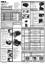
OPERATION MANUAL Quick Guide
1 Check the Product List
①
Mount the hood
on the lens
If the lens cap is attached, please
remove the cap first.
1. Fit the hood on the front of
the lens barrel.
2. Align the index marks.
3. Turn the hood lock knob clock-
wise to tighten the hood securely.
Index Mark
Hood
Lens Barrel
MACR
O
M
F.B
IRI
S
AM
W
RE
T
T
KJ20x8.5
B IKRSD
A 20x
I.G.
Shtl
VTR
э
Shtl
RET
э
Shtl
ձ
ղ
ճ
մ
ON
ON
ON
ON
SPAR
E
VTR
MACR
O
Locating Pin
Power/Iris
Control Cable
Bayonet Mount Ring
MAC
R
O
M
F.B
AM
W
T
Camera
③ Turn it on
Turn on the camera, and the power of the lens will be supplied.
④
Back focus adjustment
1. Select an object at an approprate distance
(20x: 2 to 5 meters, 13x: 1 to 3 meters). A
siemens star chart is preferable.
2. Set the iris fully open.
3. Set the lens to the telephoto end by turning
the zoom ring.
4. Bring the object into focus by turning the focus ring.
5. Set the lens to the widest angle by turning the zoom ring.
6. Loosen the flange back
lock screw, and turn the
flange back adjusting ring
to bring the object into
focus.
7. Repeat steps 3 to 6 a few
times until the object is
brought into focus at both the widest angle and telephoto.
8. After making sure that the object is in sharp focus, tighten
the flange back lock screw.
P
IW
M
F.B
&
0X
VTR
Shtl
Flange Back
Adjusting Ring
Flange back
Lock Screw
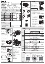
①
Zoom Operation Change-over Knob
②
Zoom Ring / Zoom Lever
③
Zoom Rocker Seesaw
④
Focus Ring
⑤
Iris Operation Mode Change-over Switch
⑥
Iris Ring
⑦
Instant Auto-Iris Switch
⑧
Connector for Remote Zoom Control
⑨
Macro Ring / Macro Button
⑩
VTR Switch
⑪
RET Switch
⑫
Flange Back Lock Screw / Flange Back
Adjusting Ring
⑬
Iris Gain Adjusting Trimmer
⑭
Locating Pin
⑮
Power / Iris Control Cable
⑯
Hood
⑰
Hood Lock Knob
⑱
Shtl Button
⑲
Memo Switch
⑳
Dip Switch
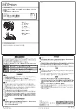
3 Adjustment before Operation
①
Read "GENERAL SAFETY INFORMATION" (back side) before using the product. The safety
cautions must be observed.
②
Read operation manual (this sheet and CD-ROM) before using the product. Keep the manual
in place for future reference.
BCTV Zoom Lens
NOTE
Set the zoom operation change-over knob
①
to “MANU”
without fail before this operation. Failure to do so may
result in malfunctioning.
NOTE
Set the iris operation change-over switch
⑤
to the “M”
without fail before this operation. Failure to do so may result
in malfunctioning.
Be sure to keep the caps in a safe
place so as not to lose them.
Hood
ZOOM
MANU.
SERVO
Hood Lock Knob
Present position
Shuttle position
Original position
Shtl
button is
held down
Shtl
button is
released
Max speed
Max speed
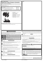
For customers who purchased
KTS type lenses
For details of operation, see "Operations using a
remote controller" on back side.
IRIS GAIN
M
A
M
A
M
A
F
Z
I
Auto/Manual Iris
Selecting Switch
Auto/Manual Zoom
Selecting Switch
Auto/Manual Focus
Selecting Switch
If your lens is remote control type,
make sure to set the three auto/
manual selecting switches to "M"
position.
⑤
Iris gain adjustment
1. Set the iris operation mode
change -over switch [for
KRSD and KRSD A type] or
the auto/manual iris selecting
switch [for KTS type] to “A“
(auto).
2. Turn over/ remove the rubber
cap which is attached here.
3. Turn the iris gain adjusting
trimmer, using a small screw-
driver to set the level as de-
sired.
C.W. : higher sensitivity
C.C.W. : lower sensitivity
4. After the iris gain adjust-
ment is completed, set it
based on the rubber cap
turned over.
,5,6*$,1
0
$
0
$
0
$
)
=
,
Iris Gain Adjusting
Trimmer
Auto/Manual Iris
Selecting Switch
Rubber
Cap
I.G.
Clockwise
Iris Gain Adjusting Trimmer
(KRSD and KRSD A type)
(KTS type)
IRIS
A
M
•
•
T
W
Iris Operation Mode
Change-over Switch
P
IW
M
F.B
&
W
T
IRIS
RE
T
KJ20x8.5
B KRSD P
S12
20x
VTR
Shtl
Lenses
Lenses
SPECIFICATION
(See PDF Operation Manual for details.
)
Model Name
Size (W
×
H
×
L)
Weight
(
Without
Hood)
Focal
Length
Zoom
Ratio
Power
Source
Current
Consumption
(
12V DC in
)
KJ20x8.5B
KRSD A
163.3mm×103.0mm×170.4mm
Approx.
1.27kg
8.5-170mm
20 x
DC12V
(
DC10-
17V
)
230 mA
KTS
113.7mm×91.4mm×170.4mm
Approx.
1.41kg
435 mA
KH20x6.4
KRSD
163.3mm×103.0mm×182.5mm
Approx.
1.27kg
6.4-128mm
230 mA
KTS
113.0mm×90.0mm×182.5mm
Approx.
1.46kg
435 mA
KT20x5B
KRSD A
163.3mm×103.0mm×171.2mm
Approx.
1.19kg
5-100mm
230 mA
KTS
113.0mm×90.0mm×171.25mm
Approx.
1.33kg
435 mA
KJ13x6B
KRSD
165.4mm×105.1mm×211.7mm
Approx.
1.59kg
6-78mm
13 x
230 mA
KTS
115.8mm×95.5mm×211.7mm
Approx.
1.73kg
435 mA
KH13x4.5
KRSD
165.4mm×105.1mm×215.3mm
Approx.
1.59kg
4.5-59mm
230 mA
Contact us
Canada: Canon Canada, Inc.
Broadcast and Communications Div.
Tel:+1(905)863-8000 Fax:+1(905)863-8003
Mexico: Canon Mexicana, S. de R.L. de C.V.
Call Center Div.
Tel:
+52 55 5249 4905
USA : Canon U.S.A., Inc.
ITCG METC
Tel:+1(800) 423-5367 (Toll Free) Fax:+1(201) 807-3344
Asia and Hong Kong, S.A.R. : Canon Hongkong Company Ltd.
ICP Marketing Div.
Tel:+852-3191-2333
Korea :
캐논코리아
컨슈머
이미징
(
주
)
제품마케팅팀
프로솔루션파트
대표전화 : (82)2-2191-8500 팩스 : (82)2-2191-8576
South and Southeast Asia : Canon Singapore Pte. Ltd.
REG ICP Sales & Marketing Div.
Tel:+65-6799-8888
Europe/Africa/Middle East : Canon Europe Ltd.
Broadcast Products Div.
Tel:+44(0)20-8588-8140 Fax:+44(0)20-8588-8929
Oceania: Canon Australia Pty. Ltd.
CCI Div.
Tel:+61(0)2-9805-2000
Please contact us if you have questions on the products.
KKJ20x8.5B KRSD A
KJ20x8.5B KTS
KH20x6.4 KRSD SY14
KJ13x6B KRSD
KJ13x6B KTS
KH13x4.5 KRSD SY14
KH20x6.4 KTS SX14A
KT20x5B KRSD A
KT20x5B KTS
MACR
O
M
F.B
⑫
⑭
⑨
⑥
②
④
⑯
IRIS
AM
W
RE
T
T
KJ20x8.5
B IKRSD
A
20x
I.G.
Shtl
VTR
э
Shtl
RET
э
Shtl
ձ
ղ
ճ
մ
ON
ON
ON
ON
SPAR
E
⑬
⑳
⑦
⑤
③
⑪
ZOOM
MANU.
SERVO
⑮
①
⑰
⑲
⑧
⑩
⑱
2 Mount and Connect
For purchasing other accessories than shown right,
please contact your dealer or below.
4 Operation
5 Advanced Operation
Lens body
The shape of the lens body and attachments are
different by models. This illustration is an example
of KJ20x8.5B KRSD A.
Lens cap
KJ13x6B KTS, KJ13x6B
KRSD, KH20x6.4 KTS only
Dust cap
Hood cap
Hood
Operation manual
•
CD-ROM
•
Quick Guide (this sheet)


