Chapter 4
4-24
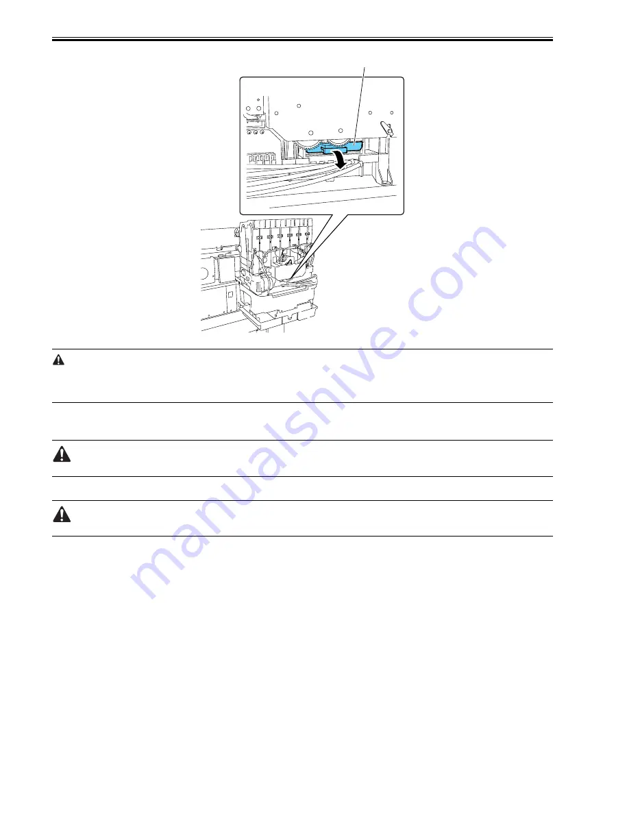
F-4-50
- If the printhead fixer lever is released with the ink supply valve to an ink tube open while the tube is filled with an ink, the ink in the tube could flow backward to
the ink tank unit, leaking through the hollow needle in the ink tank.
- If an ink supply valve remains open, as on occurrence of an ink supply valve open/close error, remove the valve motor unit and (see Disassembly/Reassembly >
Points to Note on Disassembly/Reassembly > Ink Tank Units) and close the ink supply valve.
4.3.16 Draining the ink
0014-8993
There are two ways to drain the ink passage of inks: automatic and manual.
Be sure to drain the ink from the ink passage to prevent ink leakage before disassembling any component of the ink passage or reshipping the printer.
1. Automatic Ink Drain
Execute Automatic Ink Drain by selecting Maintenance > Move Printer from the main menu.
Execute Automatic Ink Drain once again if the printer shuts down due to a power failure or any other trouble before the operation completes.
2. Manual Ink Drain
Drain the ink passage of inks manually if any electrical component in the printer fails or firmware malfunctions or if the printer fails to be powered on.
1) Remove right circle cover (L), right circle cover (S), right side covers, left/ right the ink tank cover units. See Disassembly/Reassembly > Points to Note on
Disassembly/Reassembly > External Covers.
2) Remove the ink tanks.
3) Move the carriage to above the platen. See Disassembly/Reassembly > Points to Note on Disassembly/Reassembly > Opening the caps and moving the wiper unit.
4) Release the printhead fixer lever.
5) Open the ink supply valves to allow the inks to flow into the subtanks.
3. Draining the ink in subtanks
1) Remove ink discharge tube [1] behind each subtank and move the ink from the subtank into a container. Repeat this procedure for each additional subtank.
[1]
Содержание iPF8000 - imagePROGRAF Color Inkjet Printer
Страница 1: ...Oct 3 2006 Service Manual iPF8000 series iPF8000 ...
Страница 2: ......
Страница 6: ......
Страница 12: ...Contents ...
Страница 13: ...Chapter 1 PRODUCT DESCRIPTION ...
Страница 14: ......
Страница 16: ......
Страница 38: ...Chapter 1 1 22 ...
Страница 39: ...Chapter 2 TECHNICAL REFERENCE ...
Страница 40: ......
Страница 68: ......
Страница 69: ...Chapter 3 INSTALLATION ...
Страница 70: ......
Страница 72: ......
Страница 92: ......
Страница 93: ...Chapter 4 DISASSEMBLY REASSEMBLY ...
Страница 94: ......
Страница 96: ......
Страница 124: ......
Страница 125: ...Chapter 5 MAINTENANCE ...
Страница 126: ......
Страница 128: ......
Страница 130: ......
Страница 131: ...Chapter 6 TROUBLESHOOTING ...
Страница 132: ......
Страница 173: ...Chapter 7 SERVICE MODE ...
Страница 174: ......
Страница 176: ......
Страница 189: ...Chapter 8 ERROR CODE ...
Страница 190: ......
Страница 192: ......
Страница 198: ......
Страница 199: ...Oct 3 2006 ...
Страница 200: ......


