Chapter 6
6-4
6.2.2 Laser Light Emission Control
0020-0857
imageCLASS MF9170c / imageCLASS MF9150c / imageCLASS MF8450c
In this machine, the laser diode ON/OFF is controlled according to the laser light emission mode.
The laser light emission mode is determined based on the combination of the laser control signals (LD_CTL 0 to 2) that is output by the DC controller.
The laser driver IC receives the laser control signals from the DC controller and emits the laser diode according to the laser light emission mode.
6.2.3 Laser Light Intensity Control
0020-0858
imageCLASS MF9170c / imageCLASS MF9150c / imageCLASS MF8450c
In this machine, the laser light intensity is switched according to the rotational speed of the scanner motor.
The laser light intensity switch signal (LDPWRH) that is output by the DC controller controls switching the laser light intensity.
The laser driver IC receives the laser light intensity switch signal from the DC controller and switches the laser light intensity.
6.2.4 Image Masking Control
0019-5008
imageCLASS MF9170c / imageCLASS MF9150c / imageCLASS MF8450c
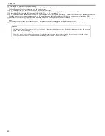
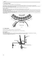
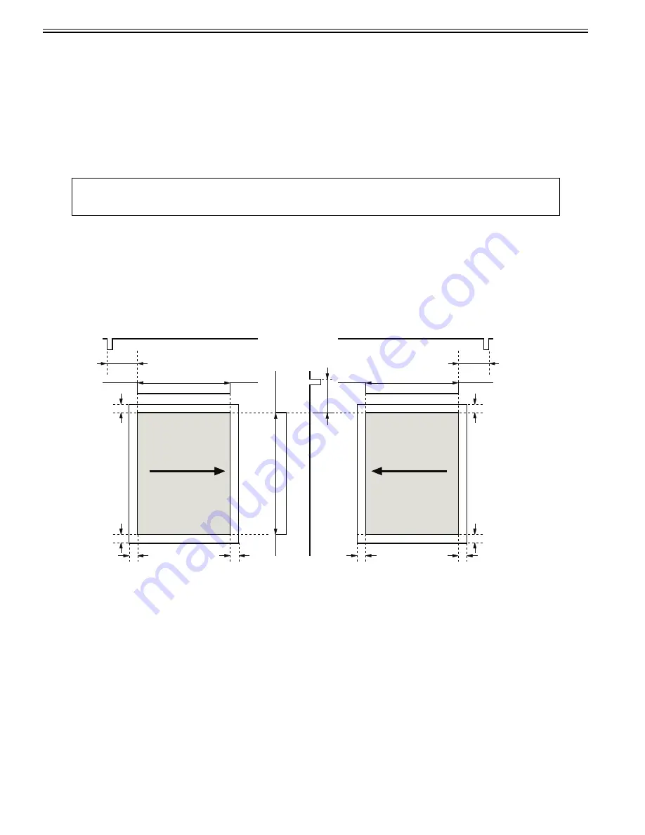
In the DC controller, the image masking control is performed to regulate laser beam emission in non-image area that BD detection is not performed on.
The DC controller puts the laser driver circuit into LD forced OFF mode while the laser beam scans the non-image area that BD detection is not performed on. This
is called the image masking status, and the laser diode does not emit light even if the video signals are sent because it is forcedly OFF in LD forced Off mode.
The timing to start the image masking control depends on the paper size information that DC controller receives from the main controller. (There is no cassette
paper size detection function in this equipment.)
F-6-3
- The colored area indicates the area where an image can be scanned by the laser beam.
- The times T1, T2, T3, T4 and T5 depend on the paper size.
- The T1 time depends on the color.
- If the main controller does not specify the paper size with a paper size command at manual feed pickup operation, the printer cannot detect the paper width. In
such a case, the T1 to T3 are automatically set for letter size but T5 is set according to the paper length detected by the manual feed paper sensor (SR707).
6.2.5 Failure Detection
0019-5009
imageCLASS MF9170c / imageCLASS MF9150c / imageCLASS MF8450c
In the DC controller, the failure in the laser diode is detected.
The laser driver IC converts the laser current of the laser diodes into voltage value (laser current output signal: PDOUT) during the initial APC period and sends it
to the DC controller.
If the voltage value equivalent to the laser current output signal is below the specified value, the DC controller presumes the laser diode failure, stops the printer
engine, and displays "E100 (optical unit failure)" on the control panel.
MEMO:
The process speed varies according to the paper type. (See 'Feed Speed Control' in Pickup and Feed System.)
When changing the process speed, the rotational speed of the scanner motor needs to be changed. If not switching the laser light intensity, a fault in image density
may occur.
2 mm
2 mm
2 m
m
2 m
m
/BDI
T3
T2
2 mm
2 mm
2 m
m
2 m
m
T2
/BDI
T1
T4
/T
OP
T5
Right/Left margin
masking
C/Bk Image masking
Y/M Image masking
T
op/Bottom
margin masking
Right/Left margin
masking
Scanning direction
Scanning direction
Содержание imageCLASS MF8450c
Страница 16: ...Chapter 1 Introduction ...
Страница 55: ...Chapter 2 Basic Operation ...
Страница 61: ...Chapter 3 Main Controller ...
Страница 75: ...Chapter 4 Original Exposure System ...
Страница 88: ...Chapter 5 Original Feeding System ...
Страница 105: ...Chapter 6 Laser Exposure ...
Страница 113: ...Chapter 7 Image Formation ...
Страница 150: ...Chapter 8 Pickup and Feed System ...
Страница 184: ...Chapter 9 Fixing System ...
Страница 200: ...Chapter 10 External and Controls ...
Страница 230: ...Chapter 11 Maintenance and Inspection ...
Страница 233: ...Chapter 12 Measurement and Adjustments ...
Страница 237: ...Chapter 13 Correcting Faulty Images ...
Страница 251: ...Chapter 13 13 13 13 3 5 PCBs 13 3 5 1 PCBs 0019 5065 imageCLASS MF9170c imageCLASS MF9150c imageCLASS MF8450c ...
Страница 256: ...Chapter 13 13 18 F 13 19 21 22 28 29 30 31 24 14 15 16 23 26 25 32 27 20 19 18 17 2 13 6 10 33 1 8 4 3 12 11 5 7 9 ...
Страница 260: ...Chapter 14 Error Code ...
Страница 272: ...Chapter 15 Special Management Mode ...
Страница 280: ...Chapter 16 Service Mode ...
Страница 322: ...Chapter 17 Upgrading ...
Страница 327: ...Chapter 17 17 4 3 Click Next F 17 4 4 Select a USB connected device and click Next F 17 5 ...
Страница 328: ...Chapter 17 17 5 5 Click Start F 17 6 6 Click Yes F 17 7 Download will be started F 17 8 ...
Страница 330: ...Chapter 18 Service Tools ...
Страница 334: ...Appendix ...
Страница 349: ......

