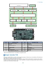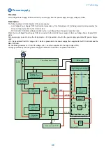
External device
Network Interface
CPU
DRAM
FLASH
MEMORY
WIFI interface
FAX interface
NCU PCB
Wireless Lan PCB
Engine controller PCB
USB interface
Video interface
Main controller PCB
J9
J5
J4
J16
J11
J12
J13
J14
J18
J8
J1
J3
J7
J10
No.
Destination / Role
No.
Destination / Role
J1
Multi-purpose Tray Sensor
J10 *
LAN Cable
J3
Not used
J11
Reader Motor
J4
Engine Controller PCB
J12 *
ADF Document Sensor/ADF Document End Sen-
sor
J5 *
Wireless Lan PCB
J13 *
ADF Solenoid
J7
USB
J14
Contact Image Sensor
J8
Control Panel PCB
J16 *
ADF Motor
J9
Low Voltage Power Supply PCB
J18 *
NCU PCB
*: May not be installed according to the specification of applicable model.
Engine Controller PCB
The Engine Controller PCB is a circuit to control the operation sequences of this machine, and controlled by DC Controller and
High Voltage Power Supply in the Engine Controller PCB.
When the DC power is supplied through the low voltage power supply, the DC Controller starts to control the printer operation.
Then the DC Controller drives loads such as laser, motors, solenoids etc. according to the image data that is input by the main
controller when status becomes stand-by mode.
2. Technology
32
Содержание imageCLASS MF264dw
Страница 13: ...Product Overview 1 Product Lineup 6 Features 8 Specifications 9 Parts Name 14 ...
Страница 14: ...Product Lineup Host machine MF269dw MF267dw MF266dn MF264dw MF263dn MF261d 1 Product Overview 6 ...
Страница 67: ...Consumable Parts Consumable parts are not required in this machine 3 Periodical Service 59 ...
Страница 68: ...Periodical Service No periodic services are required to this machine 3 Periodical Service 60 ...
Страница 77: ... SADF Unit Reader Unit 1 2 No Name 1 SADF Unit 2 Reader Unit 4 Parts Replacement and Cleaning 69 ...
Страница 78: ... Copyboard Cover Reader Unit 1 2 No Name 1 Copyboard Cover 2 Reader Unit 4 Parts Replacement and Cleaning 70 ...
Страница 89: ...3 80 mm 80 mm 4 Parts Replacement and Cleaning 81 ...
Страница 92: ... If the Fax is not installed 3x 2x 1x 2 60 mm 3 4 Parts Replacement and Cleaning 84 ...
Страница 96: ...3 4 Parts Replacement and Cleaning 88 ...
Страница 97: ...4 5 4 Parts Replacement and Cleaning 89 ...
Страница 105: ...2 3 1x 4 Parts Replacement and Cleaning 97 ...
Страница 106: ...4 CAUTION When placing the units do NOT damage the Flat Cable and the Harness 4 Parts Replacement and Cleaning 98 ...
Страница 108: ... Procedure CAUTION Do not damage the White Guide Plate 1 2 4 Parts Replacement and Cleaning 100 ...
Страница 110: ...5 6 4x 1x 1x 7 4 Parts Replacement and Cleaning 102 ...
Страница 115: ...3 4 5 4 Parts Replacement and Cleaning 107 ...
Страница 116: ...6 4 Parts Replacement and Cleaning 108 ...
Страница 122: ...2 3 4 4 Parts Replacement and Cleaning 114 ...
Страница 124: ...1 2 2x 3 4 4 Parts Replacement and Cleaning 116 ...
Страница 127: ...2 3 4 2x 1x 5 4 Parts Replacement and Cleaning 119 ...
Страница 129: ...3 4 2x 1x 5 6 4 Parts Replacement and Cleaning 121 ...
Страница 132: ...5 2x 4 Parts Replacement and Cleaning 124 ...
Страница 138: ...2 1x 3 1x 4 4 Parts Replacement and Cleaning 130 ...
Страница 140: ... Procedure 1 2 4 Parts Replacement and Cleaning 132 ...
Страница 144: ... Procedure 1 2 3 2x 4 Parts Replacement and Cleaning 136 ...
Страница 146: ...3 4 4 Parts Replacement and Cleaning 138 ...
Страница 147: ...5 4 Parts Replacement and Cleaning 139 ...
Страница 153: ...1 2 3 4 4 Parts Replacement and Cleaning 145 ...
Страница 155: ...1 2 2x 3 4 4 Parts Replacement and Cleaning 147 ...
Страница 158: ...2 3 4 2x 1x 5 4 Parts Replacement and Cleaning 150 ...
Страница 160: ...3 4 2x 1x 5 6 4 Parts Replacement and Cleaning 152 ...
Страница 163: ...5 2x 4 Parts Replacement and Cleaning 155 ...
Страница 166: ...2 2x 1x 1x 3 1x 1x 4 Parts Replacement and Cleaning 158 ...
Страница 170: ...2 2x 3 4 2x 4 Parts Replacement and Cleaning 162 ...
Страница 173: ...2 3 4 2x 1x 5 4 Parts Replacement and Cleaning 165 ...
Страница 175: ...3 4 2x 1x 5 6 4 Parts Replacement and Cleaning 167 ...
Страница 178: ...5 2x 4 Parts Replacement and Cleaning 170 ...
Страница 180: ...Controller System Removing the Control Panel Unit Procedure 1 2 4x 3 4 Parts Replacement and Cleaning 172 ...
Страница 183: ...2 4x 4 Parts Replacement and Cleaning 175 ...
Страница 186: ...2 3 If the Fax is installed 4x If the Fax is not installed 4x 4 Parts Replacement and Cleaning 178 ...
Страница 188: ... If the Fax is not installed 6 2x 1x 7 3x 8 2x 1x 4 Parts Replacement and Cleaning 180 ...
Страница 191: ...4 1x 5 1x 6 3x 4 Parts Replacement and Cleaning 183 ...
Страница 199: ... Procedure 1 3x 2x 4 Parts Replacement and Cleaning 191 ...
Страница 201: ... If the Fax is not installed 2 4x 3 4 Parts Replacement and Cleaning 193 ...
Страница 208: ...4 4 Parts Replacement and Cleaning 200 ...
Страница 211: ...3 2x 4 1x 4 Parts Replacement and Cleaning 203 ...
Страница 213: ...2 3 4x 4 4 Parts Replacement and Cleaning 205 ...
Страница 217: ...3 1x 1x 4 5 2x 6 4 Parts Replacement and Cleaning 209 ...
Страница 218: ...7 8 9 4 Parts Replacement and Cleaning 210 ...
Страница 223: ...4 4 Parts Replacement and Cleaning 215 ...
Страница 228: ...Adjustment 5 Adjustment at Parts Replacement 221 ...
Страница 230: ...Troubleshooting 6 Test Print 223 Troubleshooting Items 226 Debug Log 228 Version Upgrade 231 ...
Страница 242: ...Error Jam Alarm 7 Overview 235 Error Code 238 Jam Code 241 Alarm Code 243 ...
Страница 251: ...Alarm Code This machine does not have any Alarm Code 7 Error Jam Alarm 243 ...
Страница 287: ...APPENDICES Service Tools 280 General Circuit Diagram 281 Backup Data 283 ...

