


im2520f
– 6 –
4032-7744-02
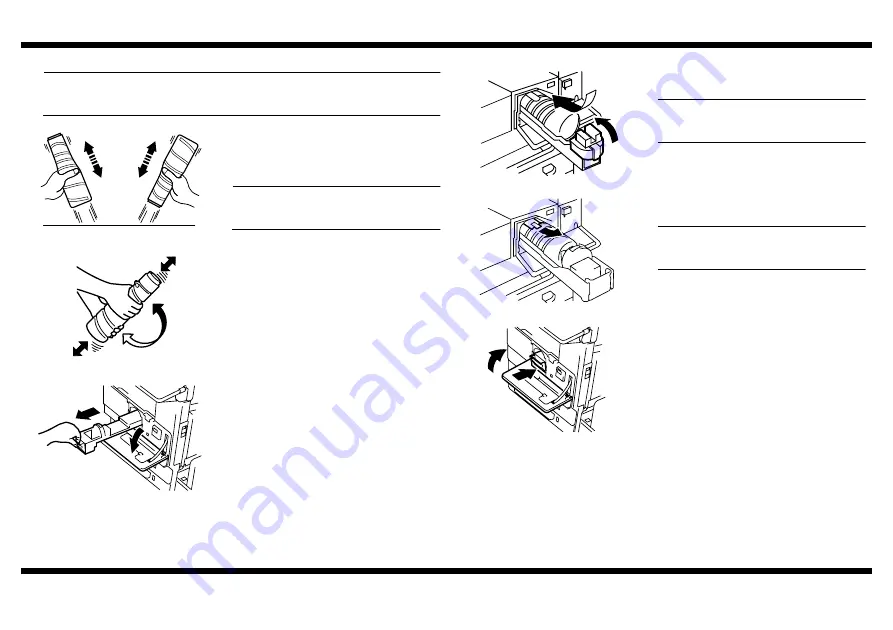
■
Installing the Toner Bottle
NOTE
The Toner Bottle is not shipped with the copier. Purchase one that is separately
available.
1. From a height of about 10 cm, tap the Toner
Bottle against a table or other hard object
four to five times. Then turn it upside down
and repeat the same procedure.
NOTE
Toner can be caked in the Toner Bottle. Be
sure to perform this procedure.
1166O228AA
2. Shake the Toner Bottle well about five times
in the vertical direction. Then, turn it over
and repeat the same procedure.
1166O095AA
3. Open the Front Door and slide the Toner
Hopper out of the copier.
4030U018AA
4. Open the Toner Holder and mount the Toner
Bottle.
NOTE
Place the Toner Bottle so that its seal
surface faces upward.
5. Close the Toner Holder.
4030U019AB
6. Gently peel off the seal toward you from the
bottle.
NOTE
Perform this procedure slowly, as toner can
burst out when the seal is peeled off.
4030U032AA
7. Slide the Toner Hopper back into the copier
until it clicks into position. Then, close the
Front Door.
4030U020AA
Содержание im2020
Страница 1: ...SETUP INSTRUCTIONS im2020 2520 3520 2520f Copier and Peripherals...
Страница 2: ...BLANK PAGE...
Страница 4: ...BLANK PAGE...
Страница 6: ...BLANK PAGE...
Страница 14: ...BLANK PAGE...
Страница 32: ...BLANK PAGE...
Страница 42: ...BLANK PAGE...
Страница 52: ...BLANK PAGE...
Страница 60: ...BLANK PAGE...
Страница 72: ...BLANK PAGE...
Страница 102: ...BLANK PAGE...
Страница 104: ......
Страница 126: ...BLANK PAGE...
Страница 136: ...BLANK PAGE...


