


Chapter 7
7-7
7.5 Parts Replacement Procedure
7.5.1 Main Motor
7.5.1.1 Preparation for Removing Main Motor
0020-2709
i-SENSYS MF4300dn / i-SENSYS MF4350d / i-SENSYS MF4380dn / i-
SENSYS MF4310/4318 / i-SENSYS MF4320d / i-SENSYS MF4330d / i-
SENSYS MF4340d / i-SENSYS D450d / i-SENSYS MF4370dn
1) Remove the front cover.
(page 9-2)
Reference[Removing the Front Cov-
er]
2) Remove the right cover.
(page 9-2)
Reference[Removing the Right Cov-
er]
3) Remove the left cover.
(page 9-3)
Reference[Removing the Left Cover]
4) Remove the DCNT PCB.
(page 9-6)
Reference[Removing the DCNT
PCB]
5) Remove the laser scanner unit.
(page 5-5)
Reference[Removing the La-
ser Scanner Unit]
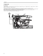
7.5.1.2 Removing Main Motor
0020-2710
i-SENSYS MF4300dn / i-SENSYS MF4350d / i-SENSYS MF4380dn / i-
SENSYS MF4310/4318 / i-SENSYS MF4320d / i-SENSYS MF4330d / i-
SENSYS MF4340d / i-SENSYS D450d / i-SENSYS MF4370dn
1) Remove the 2 screws [1], and remove the main motor [2].
F-7-5
7.5.2 Separation Pad
7.5.2.1 Preparation for Removing Separation Pad
0020-2711
i-SENSYS MF4300dn / i-SENSYS MF4350d / i-SENSYS MF4380dn / i-
SENSYS MF4310/4318 / i-SENSYS MF4320d / i-SENSYS MF4330d / i-
SENSYS MF4340d / i-SENSYS D450d / i-SENSYS MF4370dn
1) Remove the front cover.
(page 9-2)
Reference[Removing the Front Cov-
er]
2) Remove the right cover.
(page 9-2)
Reference[Removing the Right Cov-
er]
3) Remove the left cover.
(page 9-3)
Reference[Removing the Left Cover]
4) Remove the rear cover.
(page 9-2)
Reference[Removing the Rear Cover]
7.5.2.2 Removing Separation Pad
0020-2712
i-SENSYS MF4300dn / i-SENSYS MF4350d / i-SENSYS MF4380dn / i-
SENSYS MF4310/4318 / i-SENSYS MF4320d / i-SENSYS MF4330d / i-
SENSYS MF4340d / i-SENSYS D450d / i-SENSYS MF4370dn
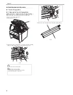
1) Remove the 2 screws [1], and remove the separation pad [2].
F-7-6
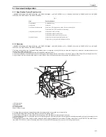
7.5.3 Pickup Roller
7.5.3.1 Removing Pickup Roller
0020-2713
i-SENSYS MF4300dn / i-SENSYS MF4350d / i-SENSYS MF4380dn / i-
SENSYS MF4310/4318 / i-SENSYS MF4320d / i-SENSYS MF4330d / i-
SENSYS MF4340d / i-SENSYS D450d / i-SENSYS MF4370dn
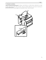
1) Open the scanner unit [1].
2) Open the printer cover [2].
F-7-7
3) Remove the pickup roller [2] by moving the 2 claws [1] to each end.
F-7-8
[1]
[2]
[1]
[1]
[2]
Do not touch the roller with bare hands.
[1]
[2]
[1]
[1]
[2]
[1]
[2]
Содержание i-SENSYS MF4300dn
Страница 1: ...Aug 22 2008 Service Manual MF4300 Series ...
Страница 2: ......
Страница 6: ......
Страница 12: ...Contents 15 1 1 Solvents Lubricants Table 15 1 ...
Страница 13: ...Chapter 1 Introduction ...
Страница 14: ......
Страница 16: ......
Страница 32: ......
Страница 33: ...Chapter 2 Basic Operation ...
Страница 34: ......
Страница 36: ......
Страница 38: ......
Страница 39: ...Chapter 3 Original Exposure System ...
Страница 40: ......
Страница 42: ......
Страница 44: ...Chapter 3 3 2 F 3 1 ...
Страница 49: ...Chapter 4 Original Feeding System ...
Страница 50: ......
Страница 52: ......
Страница 55: ...Chapter 4 4 3 F 4 6 ...
Страница 66: ......
Страница 67: ...Chapter 5 Laser Exposure ...
Страница 68: ......
Страница 70: ......
Страница 73: ...Chapter 5 5 3 ...
Страница 76: ......
Страница 77: ...Chapter 6 Image Formation ...
Страница 78: ......
Страница 80: ......
Страница 85: ...Chapter 7 Pickup and Feed System ...
Страница 86: ......
Страница 88: ......
Страница 96: ......
Страница 97: ...Chapter 8 Fixing System ...
Страница 98: ......
Страница 100: ......
Страница 102: ...Chapter 8 8 2 F 8 2 1 Pressure roller 2 Fixing film H1 Fixing heater TH1 Thermistor TP1 Temperature fuse 1 TP1 TH1 H1 2 ...
Страница 108: ......
Страница 109: ...Chapter 9 External and Controls ...
Страница 110: ......
Страница 112: ......
Страница 121: ...Chapter 10 Maintenance and Inspection ...
Страница 122: ......
Страница 124: ......
Страница 128: ......
Страница 129: ...Chapter 11 Measurement and Adjustments ...
Страница 130: ......
Страница 132: ......
Страница 135: ...Chapter 12 Correcting Faulty Images ...
Страница 136: ......
Страница 138: ......
Страница 144: ...Chapter 12 12 6 2 DCNT PCB 3 Power supply PCB 4 High voltage PCB SW301 Interlock switch ...
Страница 145: ...Chapter 13 Error Code ...
Страница 146: ......
Страница 147: ...Contents Contents 13 1 Error Code 13 1 13 1 1 Error Code Outline 13 1 13 1 2 Error Code 13 1 ...
Страница 148: ......
Страница 153: ...Chapter 14 Service Mode ...
Страница 154: ......
Страница 156: ...Contents 14 3 2 3 Sensor test 14 16 14 3 2 4 Key test 14 16 ...
Страница 174: ......
Страница 175: ...Chapter 15 Service Tools ...
Страница 176: ......
Страница 177: ...Contents Contents 15 1 Service Tools 15 1 15 1 1 Solvents Lubricants Table 15 1 ...
Страница 178: ......
Страница 180: ......
Страница 181: ...Aug 22 2008 ...
Страница 182: ......


