Canon BW PCL PRINTER KIT-J1 Скачать руководство пользователя страница 15

Chapter 1

1-3

Non-default paper

T-1-5

Supported Paper Types

T-1-6

Finishing

T-1-7

N/A: not available

Resolution


600dpi

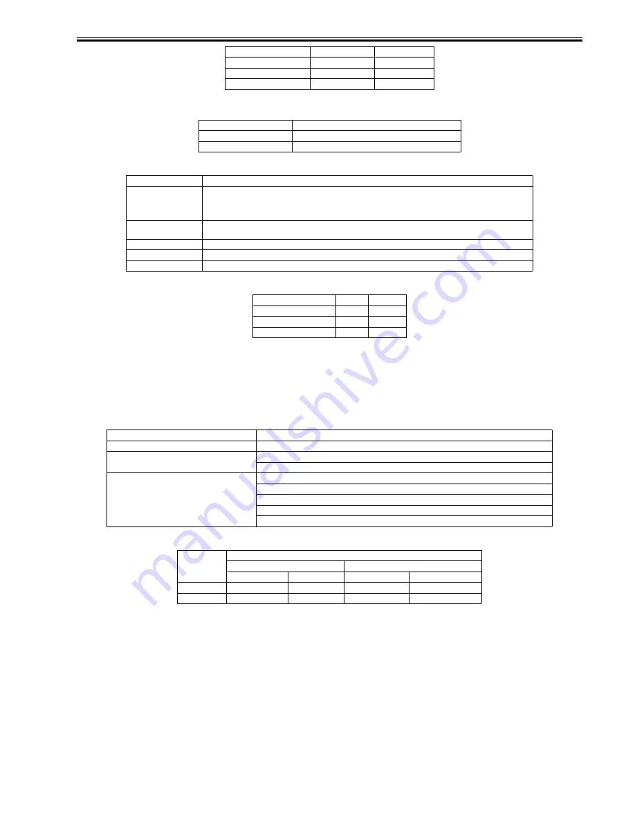
1.2.2 Specifications

0011-1409

The main specifications and features of the kit are as shown below. 

<Characteristics>

- printing is virtually immediate

- output is close to screen display

T-1-8

Effective print area

T-1-9

MONARCH

98.4

190.5

C5 ISO

162.0

229.0

B5 ISO

176.0

250.0

DL

110.0

220.0

Non-default paper 

iR2020/2016

Minimum

95.0 x 148.0 mm

Maximum

297.0 x 431.8 mm

Paper Type

Paper Size

PLAIN
COLOR
RECYCLED
HEAVY

A3, B4, A4/A4R, B5/B5R, A5/A5R, 11x17, LGL, LTR/LTRR, STMT/STMTR, EXEC, Local standard, Custom paper

BOND
LABELS

A3, B4, A4/A4R, B5/B5R, A5/A5R, 11x17, LGL, LTR/LTRR, STMT/STMTR, EXEC, Custom paper

OHP

A4, LTR

3-hole Punch

LTR/LTRR

Envelope

COM10, MONARCH, C5ISO, B5ISO, DL

Finisher Shift 

Staple

None

N/A

N/A

Inner 2way Tray

N/A

N/A

Finisher-U1

OK

OK

Specifications  

PCL

Data processing resolution

600 dpi

Effective print area

main scanning direction: 1/6 inch
sub scanning direction: 1/6 inch

Supported operating systems

Windows 2000 Professional/Server/Advanced Server
Windows XP Home Edition/Professional Edition
Windows Server 2003 Stadard Edition/Enterprise Edition
Windows 98/98SE/ME
Windows NT4.0 Workstation/Server

PCL
Effective print area

End of Papaer

Main scaning

Sub scaning

Main scaning

Sub scaning

Minimum

86.53mm

139.53mm

4.23mm

4.23mm

Maximum

288.53mm

423.33mm

4.23mm

4.23mm

Содержание BW PCL PRINTER KIT-J1

Страница 1: ...Sep 14 2005 Service Manual Canon BW PCL PRINTER KIT J1 ...

Страница 2: ......

Страница 3: ... need arises In the event of major changes in the contents of this manual over a long or short period Canon will issue a new edition of this manual The following paragraph does not apply to any countries where such provisions are inconsistent with local law Trademarks The product names and company names used in this manual are the registered trademarks of the individual companies Copyright This ma...

Страница 4: ...quiring care to avoid combustion fire Indicates an item prohibiting disassembly to avoid electric shocks or problems Indicates an item requiring disconnection of the power plug from the electric outlet Indicates an item intended to provide notes assisting the understanding of the topic in question Indicates an item of reference assisting the understanding of the topic in question Provides a descri...

Страница 5: ...sed to indicate Low The voltage value how ever differs from circuit to circuit In addition the asterisk as in DRMD indicates that the DRMD signal goes on when 0 In practically all cases the internal mechanisms of a microprocessor cannot be checked in the field Therefore the operations of the microprocessors used in the machines are not discussed they are explained in terms of from sensors to the i...

Страница 6: ......

Страница 7: ...re LCD 1 1 1 1 2 ROM for starting PCL LCD 1 2 1 2 Specifications 1 2 1 2 1 PCL Printer Driver 1 2 1 2 2 Specifications 1 3 Chapter 2 Installation 2 1 Checking components 2 1 2 1 1 Checking the Contents 2 1 2 2 Installation procedure 2 1 2 2 1 Mounting to the Host Machine 2 1 2 2 2 Checking the Connection 2 6 ...

Страница 8: ......

Страница 9: ...Chapter 1 Specifications ...

Страница 10: ......

Страница 11: ...ontents Contents 1 1 Product composition 1 1 1 1 1 Operating conditions of Hardware LCD 1 1 1 1 2 ROM for starting PCL LCD 1 2 1 2 Specifications 1 2 1 2 1 PCL Printer Driver 1 2 1 2 2 Specifications 1 3 ...

Страница 12: ......

Страница 13: ...e determied The followings are the models that accessories can be added iR2016 Upgradeable Model T 1 2 The 256MB RAM bundled with the PCL_PRINTER_KIT J1kit is the same one as a 256MB RAM which is set as iR 256MB Expansion RAM D1 0449B001AA Non Upgradeable Model Merchandise control name iR2020J 230V iR2020J CN 220V iR2016J 120V iR2016 EUR 230V iR2016J 230V iR2016J CN 220V iR2016J KR 220V Point of d...

Страница 14: ... by the driver setting If a device font is used the Raster Mode will handle data the same as the HP GL 2 Mode If not the following restrictions will be imposed GDI Raster Fonts unavailable 1 byte fonts such as Courier MS Sans Serif MS Serif etc GDI Vector Fonts available 1 byte fonts such as Modern Roman Script etc TrueType Fonts available 1 byte fonts such as Arial Courier New Symbol Times New Ro...

Страница 15: ...cal standard Custom paper BOND LABELS A3 B4 A4 A4R B5 B5R A5 A5R 11x17 LGL LTR LTRR STMT STMTR EXEC Custom paper OHP A4 LTR 3 hole Punch LTR LTRR Envelope COM10 MONARCH C5ISO B5ISO DL Finisher Shift Staple None N A N A Inner 2way Tray N A N A Finisher U1 OK OK Specifications PCL Data processing resolution 600 dpi Effective print area main scanning direction 1 6 inch sub scanning direction 1 6 inch...

Страница 16: ......

Страница 17: ...Chapter 2 Installation ...

Страница 18: ......

Страница 19: ...Contents Contents 2 1 Checking components 2 1 2 1 1 Checking the Contents 2 1 2 2 Installation procedure 2 1 2 2 1 Mounting to the Host Machine 2 1 2 2 2 Checking the Connection 2 6 ...

Страница 20: ......

Страница 21: ...o the Host Machine 0010 7632 1 Turn off the main power switch and disconnect the power plug 2 Remove the rear cover 1 4 screws 2 F 2 2 3 Remove the rear left cover 1 3 screws 2 1 32MB ROM 1 pc 2 256MB RAM 1 pc 3 Screw binding M3X4 1 pc 4 User software CD ROM 1 pc 5 Release Note 1 pc 6 User s Manual CD ROM 1 pc 1 2 3 4 5 6 1 2 ...

Страница 22: ... the image memory even after the main power switch has been turned off and the power plug has been disconnected Be sure to disconnect the IP modem cable before removing the RAM F 2 4 5 Remove the RAM cover 1 4 screws 2 F 2 5 6 Remove the 128MB RAM 1 in the direction of A 2 locking levers 2 shift in the direction of B F 2 6 7 If a UFRII LT PRINTER KIT J2 is installed perform steps 7 1 and 7 2 1 2 1...

Страница 23: ... F 2 7 7 2 Disconnect the connector 1 of the IP LAN cable 1 wire saddle 2 IP LAN cable 3 F 2 8 8 Disconnect the soft ID cable 1 1 cable clamp 2 F 2 9 9 Release the claw 1 of the cable guide and free the cable guide 2 in upward direction 2 1 2 1 2 3 1 2 ...

Страница 24: ...ews 2 F 2 11 11 Shift the 2 locking levers 1 back to their initial position F 2 12 12 Connect the connector 1 of the 32MB ROM to the connector 2 of the IP PCB 1 screw binding M3x4 3 F 2 13 13 Attach the IP cover you removed in step 10 1 2 2 2 2 1 1 1 2 3 ...

Страница 25: ...you have removed back in place cable guide soft ID cable IP LAN cable if a UFRII LT PRINTER KIT J2 is mounted 15 Attach the LAN cover removed in step 7 1 if a UFRII LT PRINTER KIT J2 is mounted When attaching the LAN cover take care not to damage the grounding plate 2 by the LAN port 1 Also after attaching the LAN cover check to make sure that the grounding plate is in firm contact with the LAN po...

Страница 26: ...hecking the Connection 0010 7789 When you have installed the kit go through the following to make sure that it is properly recognized 1 Start service mode User Mode key 2 8 Use Mode key In response SSSW appears 2 Press 5 times When REPORT has appeared press OK 3 Press once When REPORT OUTPUT has appeared press OK 4 Press 5 times When SPEC LIST has appeared press OK 5 See that a SPEC REPORT is prin...

Страница 27: ...Sep 14 2005 ...

Страница 28: ......

Отзывы: