E21
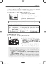
NOTE
•
Take care not to damage the drive unit cover when removing the drive unit fixing screws.
•
Use a Phillips screwdriver with a shaft diameter of 4mm or less to remove the drive unit fixing screws.
•
Never insert the removed screws into the screw holes in which the drive unit was fixed.
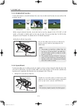
• When the lens is tilted, the zoom ring may turn and the zoom position may change. To retain the zoom position
when the lens is tilted, mount a cinema operation accessory with adjustable torque and with a pitch of 0.5.
• If the drive unit is removed, the iris ring may turn and the iris position may change. To retain the iris position,
mount a cinema operation accessory with adjustable torque and with a pitch of 0.4 on the iris ring. For details on
the operation accessory with a pitch of 0.4, contact Canon Inc. or Canon distributers & sales representatives.
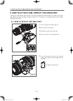
6 HOW TO ATTACH AND DETACH THE DRIVE UNIT
6
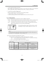
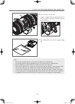
Cap the contact on the lens body.
If power is supplied from the camera when the PL
mount lens is used, remove the 12-pin cable and then
cap the connector.
7
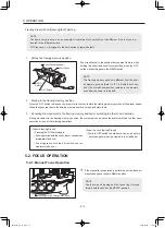
Place the detached drive unit in the supplied storage
bag.
Cap
BT1-B051-E_E_CC.indd 21
2020/02/04 11:03:04
Содержание 4573C002
Страница 2: ...ENGLISH VERSION BT1 B051 E_E_CC indd 1 2020 02 04 11 02 01 ...
Страница 7: ...BT1 B051 E_E_CC indd 6 2020 02 04 11 02 05 ...
Страница 35: ...資料集 TECHNICAL INFORMATION 资料汇编 BT1 B051 E_資料集_JEC indd 1 2020 02 13 15 28 19 ...
Страница 36: ...BT1 B051 E_資料集_JEC indd 2 2020 02 13 15 28 20 ...

