PC400 / PC410 l User’s Manual
30
Chapter 2: Switches and Connectors
30
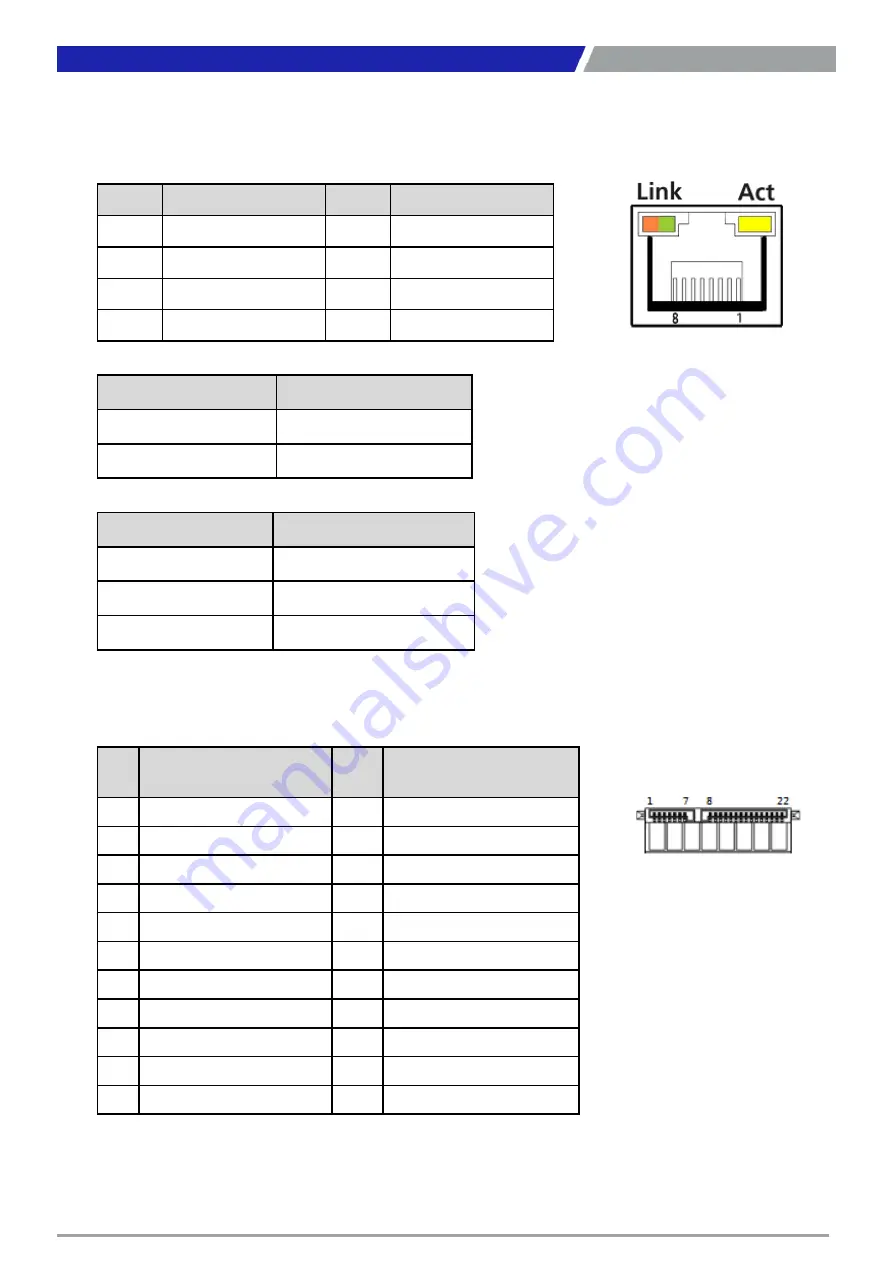
LAN1, LAN2: RJ45 with LEDs Port
Connector Type: RJ45 Connector
Pin
Definition
Pin
Definition
1
LAN_MDI0P
5
LAN_MDI2N
2
LAN_MDI0N
6
LAN_MDI1N
3
LAN_MDI1P
7
LAN_MDI3P
4
LAN_MDI2P
8
LAN_MDI3N
Link LED Status
Definition
Steady Orange
1Gbps Network Link
Steady Green
100Mbps Network Link
Off
10Mbps Network Link
Act LED Status
Definition
Blinking Yellow
Data Activity
Off
No Activity
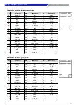
SATA with Power Connector
Pin
SATA1_1 Definition
Pin
SATA1_1 Definition
1
GND
12
GND
2
TxP
13
GND
3
TxN
14
+5V
4
GND
15
+5V
5
RxN
16
+5V
6
RxP
17
GND
7
GND
18
GND
8
NC
19
GND
9
NC
20
+12V
10
DEVSLP
21
+12V
11
GND
22
+12V
Содержание PC400 Series
Страница 1: ...PC400 Series PC Module...
Страница 8: ...Chapter 1 Product Introductions...
Страница 16: ...PC400 PC410 l User s Manual 16 1 4 Mechanical Dimensions 1 4 1 PC400 Unit mm Chapter 1 Product Introductions...
Страница 17: ...PC400 PC410 l User s Manual 17 1 4 2 PC410 Unit mm Chapter 1 Product Introductions...
Страница 18: ...Chapter 2 Switches and Connectors...
Страница 20: ...PC400 PC410 l User s Manual 20 2 1 2 Bottom View Chapter 2 Switches and Connectors...
Страница 33: ...Chapter 3 System Setup...
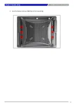
Страница 42: ...PC400 PC410 l User s Manual 3 Lock the below 6 screws M4X5L to finish assembly 42 Chapter 3 System Setup...
Страница 43: ...Chapter 4 BIOS Setup...
Страница 46: ...PC400 PC410 l User s Manual 4 3 Advanced Setup 46 Chapter 4 BIOS Setup...
Страница 71: ...Copyright 2016 C T Solution Inc All Rights Reserved www candtsolution com...


