RS02109/0814/CD
28
www.cdtechno.com
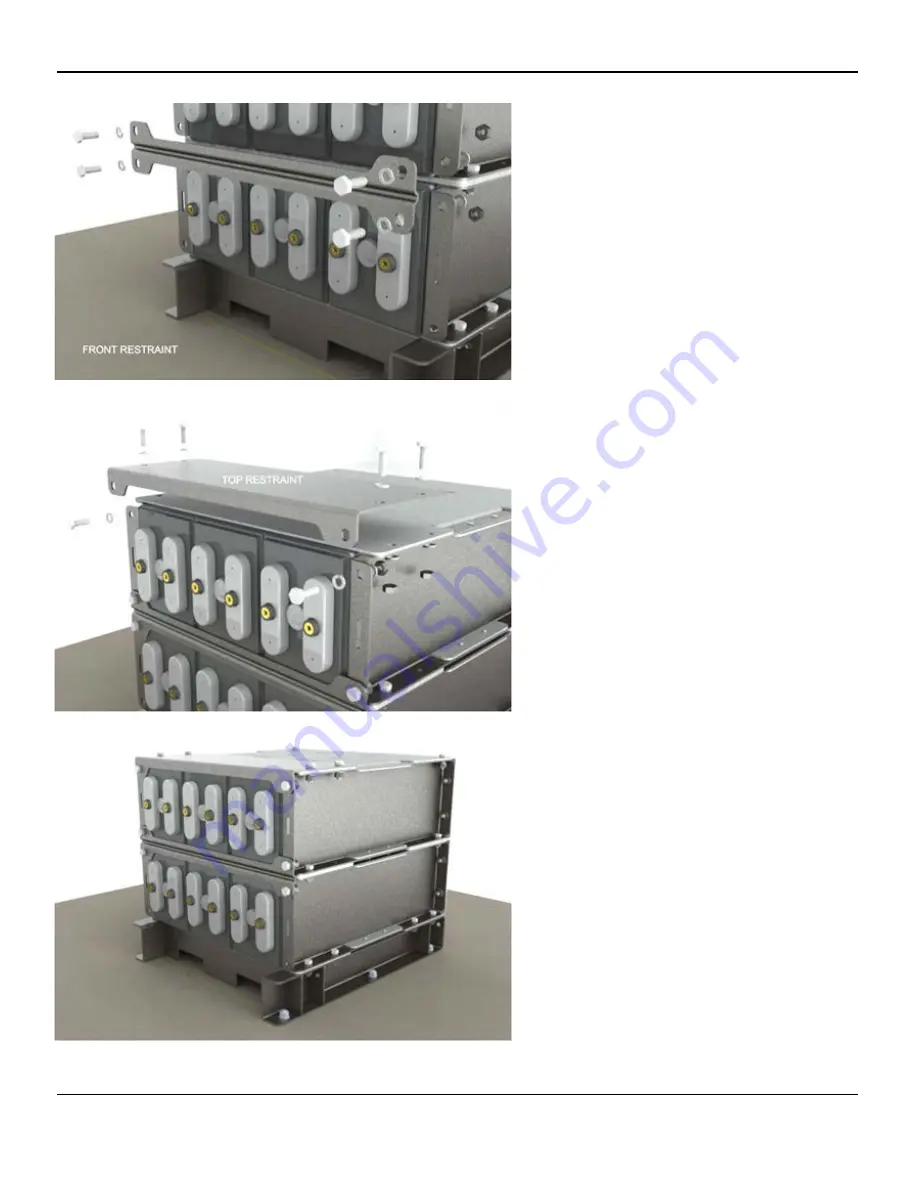
Figure A15
System Restraints
All systems are supplied from the factory with
two types of restraints. These restraints are
critical in maintaining the seismic rating of the
system and must be installed properly.
Front Restraint
Front restraints are installed between each
tier of the system to prevent cells from
shifting in the event of an earthquake. With all
of the modules properly stacked and in
agreement with the C&D layout drawing
attach the restraint bar using (4) 10mm bolt
assemblies (See Figure A15).
Top Restraint
Each system/stack will be supplied with one
top restraint. The top restraint will be installed
on the upper most module to complete the
assembly. The restraint will be installed using
(6) 10mm bolt assemblies (See Figure A16).
Final Check
Once the top restraint is attached the system
assembly is complete. Before attaching
terminal plates and making series
connections verify one last time the cell
orientation matches the supplied C&D
connection diagram.
Refer to Section 6 for mounting Terminal
Plates & inter-cell connectors.
Figure A16
Figure A17
Содержание Liberty DCS
Страница 1: ...RS02109 0814 CD 1 www cdtechno com MSE DCS...
Страница 36: ...RS02109 0814 CD 36 www cdtechno com...
Страница 37: ...RS02109 0814 CD 37 www cdtechno com...

